
Phase change cooled electrical resistor

a technology of resistors and phase changes, applied in the direction of resistors, resistor details, cooling/ventilation/heating modifications, etc., can solve the problems of resistors generating resistors may generate more heat than can be adequately transmitted to the environment by conventional means,

Inactive Publication Date: 2008-10-30
ROCKWELL AUTOMATION TECH
View PDF6 Cites 7 Cited by
  • Summary
  • Abstract
  • Description
  • Claims
  • Application Information

AI Technical Summary

Benefits of technology

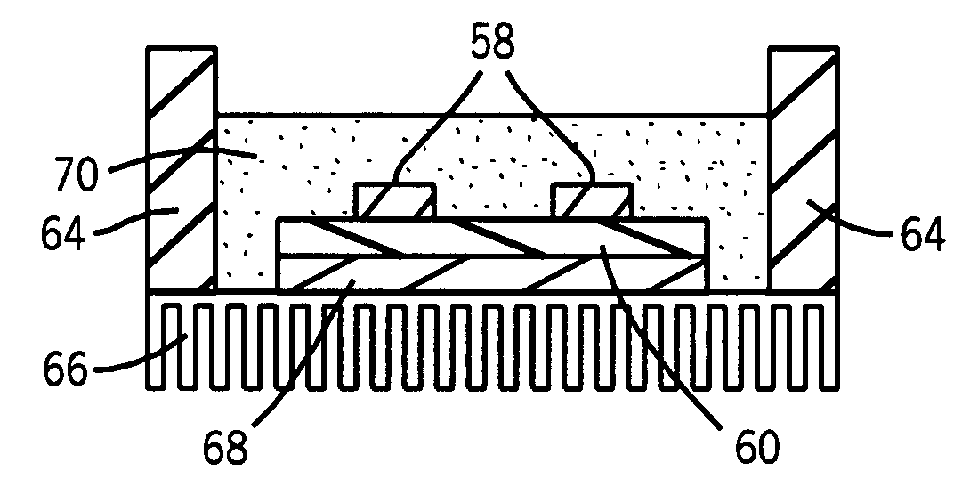
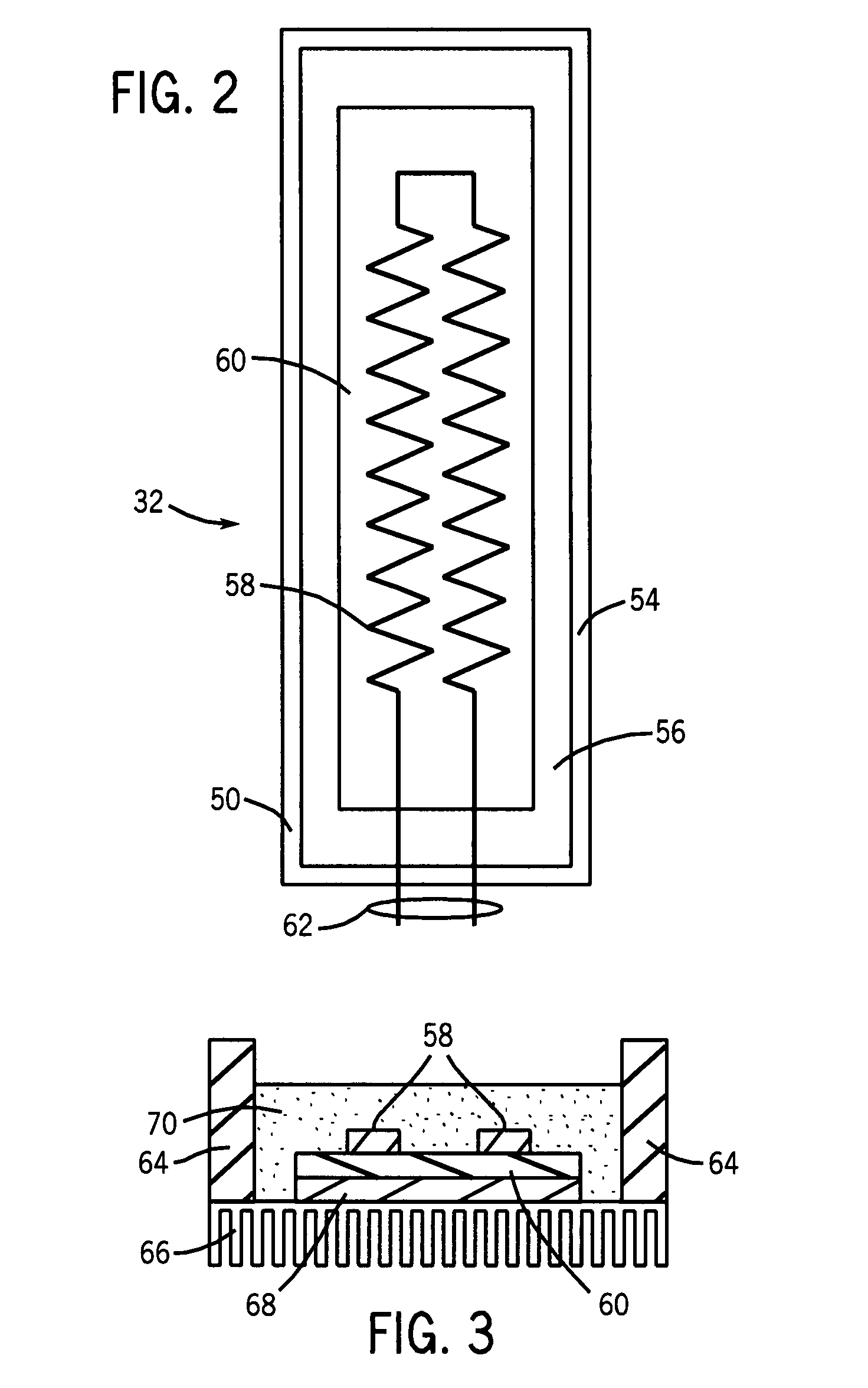
[0006]In accordance with aspects of the invention, a phase change heat spreader or cooling device is disposed adjacent to a resistor to be cooled. The resistor may take any suitable form. However, a planar resistor arrangement is particularly attractive insomuch as it may be placed in closer proximity to the heat spreader. The resistor may be placed in a modular enclosure, and the heat spreader either disposed adjacent to a side of the enclosure, or incorporated directly therein (e.g., as one side of the device. Moreover, such heat spreaders may be associated with more than one side of the enclosure.

Problems solved by technology

Because resistors develop significant heat due to their internal resistance and the current flowing through them during operation, heat dissipation is often a challenge for their use.
However, in many settings, the resistors may generate more heat than can be adequately transmitted to the environment by conventional means.
Water circulating systems are often undesirable due to their complexity and the potential for leaks.
Many conventional cooling schemes also fail adequately to reduce temperature differences or gradients in structures surrounding the resistor.

Method used


Image

  • Phase change cooled electrical resistor
  • Phase change cooled electrical resistor
  • Phase change cooled electrical resistor

Examples


Embodiment Construction

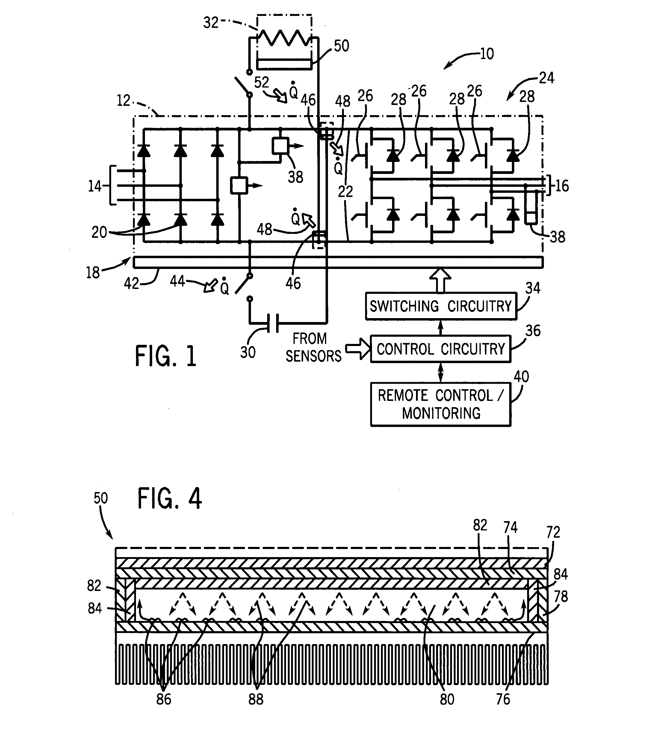
[0013]Turning now to the drawings, and referring first to FIG. 1, an exemplary power electronic circuit 10 is illustrated in which phase change heat spreaders or cooling devices are employed in accordance with aspects of the invention. In the illustrated embodiment, circuit 10 forms a power module 12, such as for a motor drive. The power module is adapted to receive three-phase power from a line side 14 and to convert the fixed frequency input power to control frequency output power delivered at a load side 16. While an inverter circuit will generally be described below as an example of an application of the present invention, it should be borne in mind throughout this discussion that the invention is not limited to this or any particular power electronic circuit. Indeed, the invention may be used in inverter applications, converter applications, AC-to-AC circuitry, AC-to-DC circuitry, DC-to-AC circuitry, and DC-to-DC circuitry. Certain of the inventive aspects may be applied in a w...


PUM


Abstract

A technique is disclosed for cooling resistive elements, such as brake resistors used in motor drives, as well as other resistors. A phase change heat spreader is thermally coupled to the resistive element and a continuous phase change cycle takes place in the heat spreader to extract heat from the resistive element. The element and heat spreader may be packaged as a modular unit or may be integrated into a system.

Description

BACKGROUND[0001]The present invention relates generally to the field of thermal management structures for power electronic circuits and the like. More particularly, the invention relates to the cooling of resistors, such as brake resistors used in inverters and other power electronic devices.[0002]Resistors are used in power electronic devices for a range of reasons. Firstly, such resistors may operatively figure as part of the overall power signal conditioning or control scheme. However, other resistors are used to dissipate energy, such as in the case of motor drives, power converters, and so forth. Such brake resistors may be associated, for example, with a DC bus extending between a rectifier and a converter (e.g., an inverter). The resistors may be switched into the circuit when necessary to dissipate energy, such as for braking an inertial load. Because resistors develop significant heat due to their internal resistance and the current flowing through them during operation, he...

Claims


Application Information

Patent Timeline
Patent Type & Authority Applications(United States)
IPC IPC(8): H01C1/08
CPCH01C1/028H01C1/082H01C1/084
Inventor LUKASZEWSKI, RICHARD A.BRUBAKER, JOHN R.GROSSKREUZ, PAUL J.GOLLHARDT, NEILRADOSEVICH, LAWRENCE D.WEISS, BRUCE W.
Owner ROCKWELL AUTOMATION TECH
Learn More