Transmitter and wireless system using the same

a wireless communication system and transmitter technology, applied in the direction of near-field systems using receivers, programme control, instruments, etc., can solve the problems of affecting the conversion will be certainly the conversion will be accompanied by a conversion loss, so as to improve the power transfer efficiency of the base station to the terminal station, the service area of the wireless communication system can be expanded, and the communication range between the base station and the terminal station

Inactive Publication Date: 2008-10-30
HITACHI LTD
View PDF22 Cites 231 Cited by
  • Summary
  • Abstract
  • Description
  • Claims
  • Application Information

AI Technical Summary

Benefits of technology

[0005]However, with an increase in the speed and capacity of the physical distribution, it is a universal society demand to enhance the capability of object detection and the information transmission capacity using electromagnetic waves, in other words, to improve the distance which electromagnetic waves will reach in a wireless system. Electromagnetic waves decrease with a transmission distance, in proportion to about the 2nd to 3rd power of the distance. Therefore, when the transmission distance increases, the electromagnetic waves radiated from a base station are reflected by an object and arrive at the base station again with remarkably decreased power. Consequently, the arrival electromagnetic waves will possess a very low tolerance property against various disturbing factors.
[0006]In such a system, a common method is to use, as a carrier for information transmission, the electromagnetic scattered field from the object to be identified, in order that the energy of the electromagnetic waves which arrive from the base station is reradiated to the base station with a conversion loss as small as possible. In order to generate a new carrier by certain means, it will be necessary to convert the high-frequency power of electromagnetic waves into an electric source power for the certain means. Actually, the conversion will be certainly accompanied with a conversion loss. In the radio transmission using electromagnetic waves, the range of electromagnetic waves will be restricted by the power to be given to a carrier. Therefore, to make the power efficiency of carrier generation maximum leads to maximizing the range of the electromagnetic waves in the system, in other words, to maximizing the application limit of the system.
[0012]The present invention has been made in view of the above circumstances and provides a transmitter and a wireless communication system using the same, to improve the power transfer efficiency from a base station to a terminal station, and to expand the communication range between the base station and the terminal station with a power below a limited value.
[0014]According to one embodiment of the present invention, the power transfer efficiency from a base station to a terminal station improves, and a communication range between the base station and the terminal station can be expanded with a power below a limit value. Therefore, it is effective in expanding the service area of the wireless communication system which uses the base station and the terminal station as the components of the system.

Problems solved by technology

Consequently, the arrival electromagnetic waves will possess a very low tolerance property against various disturbing factors.
Actually, the conversion will be certainly accompanied with a conversion loss.
With the transmission power below such specified value, many difficulties will be met in extending the communication range.

Method used


Image

  • Transmitter and wireless system using the same
  • Transmitter and wireless system using the same
  • Transmitter and wireless system using the same

Examples


first embodiment

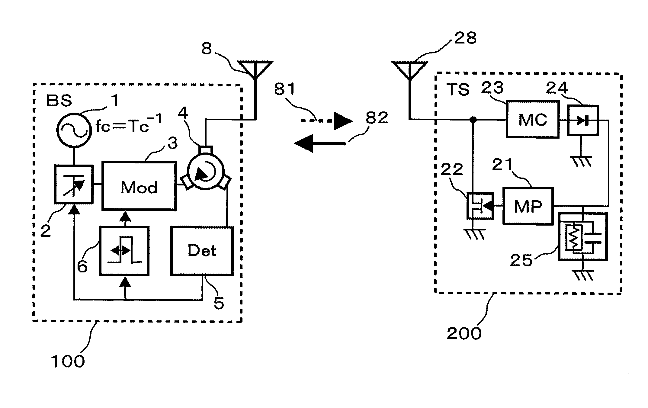
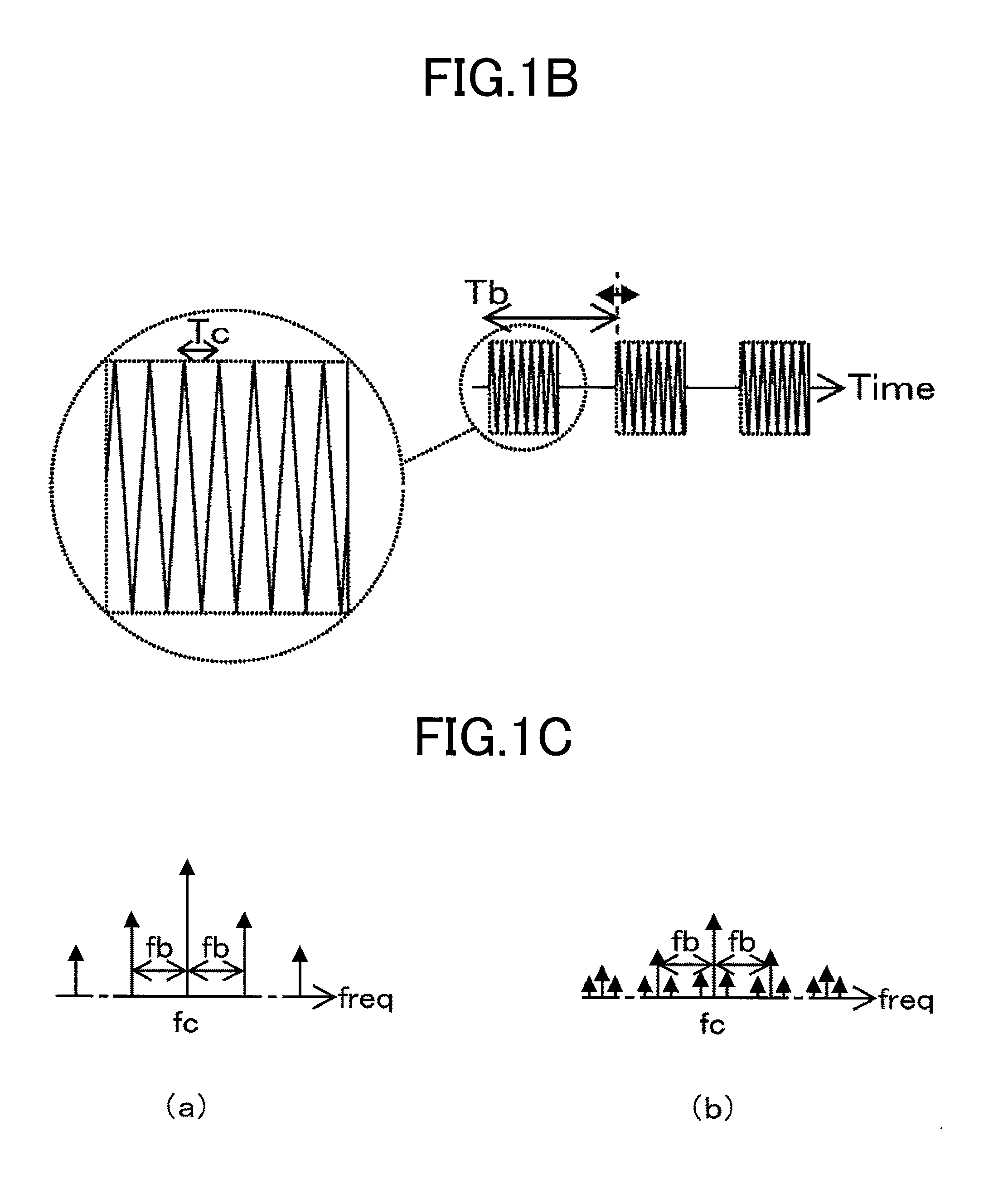
[0040]A first embodiment of the present invention is described with reference to FIGS. 1A to 1D. FIG. 1A is a block diagram illustrating constitution of a wireless system according to the first embodiment of the present invention. A base station 100 includes a carrier generation circuit 1, a variable attenuator 2, a modulation circuit 3, a circulator 4, a sideband wave detector circuit 5, a duty variable circuit 6, and a base-station antenna 8. A terminal station 200 includes a switch 22, a matching circuit 23, a rectifier circuit 24, a smoothing circuit 25, a micro-processor 21, and a terminal-station antenna 28. Electromagnetic waves which propagate space are used for the communication media between the base station and the terminal station, and intermittent transmission is performed between the base station and the terminal station.

[0041]In the base station 100, a carrier signal of frequency fc is generated by the carrier generation circuit 1 which possesses an oscillator. The ca...

second embodiment

[0068]Another embodiment of the present invention is described with reference to FIG. 7. FIG. 7 is a block diagram illustrating a waveform-equalized intermittent transmission wireless system according to another embodiment of the present invention. The present embodiment illustrated in FIG. 7 is different from the embodiment of FIG. 1 in the following points. That is, the base station 100 further includes a micro-processor 10 and a memory 11. The output of the detector circuit 5 is inputted in the micro-processor 10. The micro-processor 10 is coupled to the external memory 11, and controls a variable attenuator 2 and a duty variable circuit 6.

[0069]In the present embodiment, the micro-processor 10 included in the base station is provided with a function to perform control of the variable attenuator and the duty variable circuit, with a more advanced and more sophisticated control parameter based on the information stored in the external memory 11 in advance, using the information on...

third embodiment

[0071]Another embodiment of the present invention is described with reference to FIG. 8. FIG. 8 is a block diagram illustrating a waveform-equalized intermittent transmission wireless system according to another embodiment of the present invention. What is different from the embodiment of FIG. 1 is that the modulation circuit is realized by a switch 7. According to the present embodiment, a modulation circuit is realizable by simple circuitry.

[0072]According to the present embodiment, in addition to the effect of the first embodiment, the miniaturization of the base station of the wireless system and production cost reduction can be effectively realized.


PUM


Abstract

When supplying a power from a base station to a terminal station on radio and a distance from a base station to a terminal station is long, it becomes impossible for the terminal station to rectify the power. The feature of the present invention is found in a wireless communication system in which the peak value and duty ratio of a transmission power are controlled simultaneously, keeping the transmission power of a base station below a fixed value, thereby allowing a voltage to be applied to a diode, which is a component of a rectifier circuit possessed by a terminal station, always in excess of a threshold voltage of the diode, and energy is exchanged between the base station and the terminal station below a limit power.

Description

CLAIM OF PRIORITY[0001]The present application claims priority from Japanese application JP 2007-117510 filed on Apr. 26, 2007, the content of which is hereby incorporated by reference into this application.FIELD OF THE INVENTION[0002]The present invention relates to a transmitter and a wireless system using the same, especially, to a transmitter suitable to an RFID wireless system for example, and a wireless system using the transmitter, in which an electromagnetic wave transmitted by a base station is scattered on an unspecified object or a terminal station, and arrives at the base station again, subsequently the base station receives this arrival electromagnetic wave, and identifies information proper to the object or the terminal station.BACKGROUND OF THE INVENTION[0003]In a wireless system which uses a scattered wave as a direct carrier, the conventional technology which may be called direction division duplex (DDD) is known. In this technology, a transmitted wave and a receive...

Claims


Application Information

Patent Timeline
Patent Type & Authority Applications(United States)
IPC IPC(8): G08B13/14G06K7/00G06K17/00G06K19/07H04B1/59H04B5/02H04L27/36
CPCG06K7/0008G06K7/10217
Inventor TAKEI, KEN
Owner HITACHI LTD
Why Eureka
Try Eureka