Exposure Apparatus, Exposure Method, and Method for Producing Device
a technology of exposure apparatus and exposure method, which is applied in the direction of photomechanical apparatus, printing, instruments, etc., can solve the problems of difficult to match the substrate surface with respect to the image plane of the projection optical system, insufficient focus margin, and difficult to maintain the desired state, etc., to suppress the amount of movement of the interface, suppress the spread or expansion of the liquid immersion area, and suppress the effect of large change of the shape of the interfa
- Summary
- Abstract
- Description
- Claims
- Application Information
AI Technical Summary
Benefits of technology
Problems solved by technology
Method used
Image
Examples
first embodiment
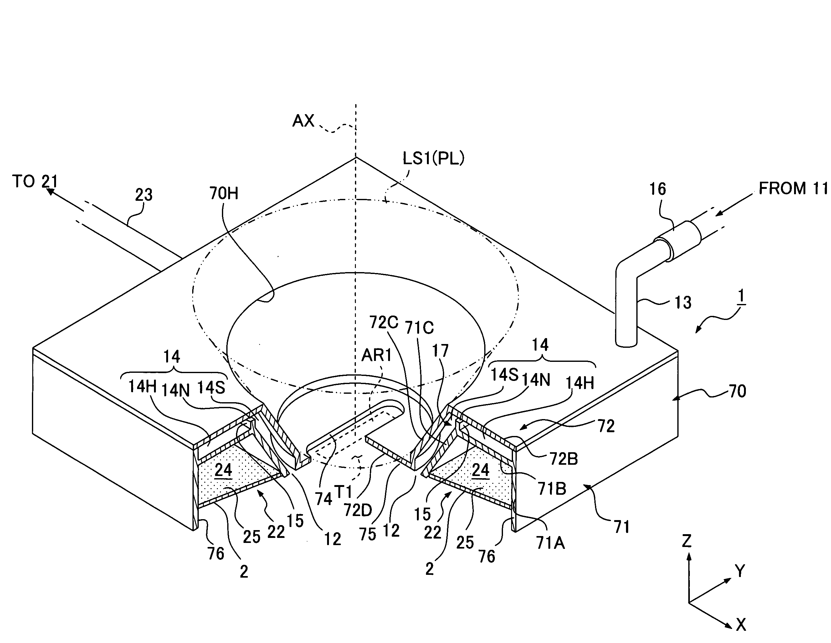
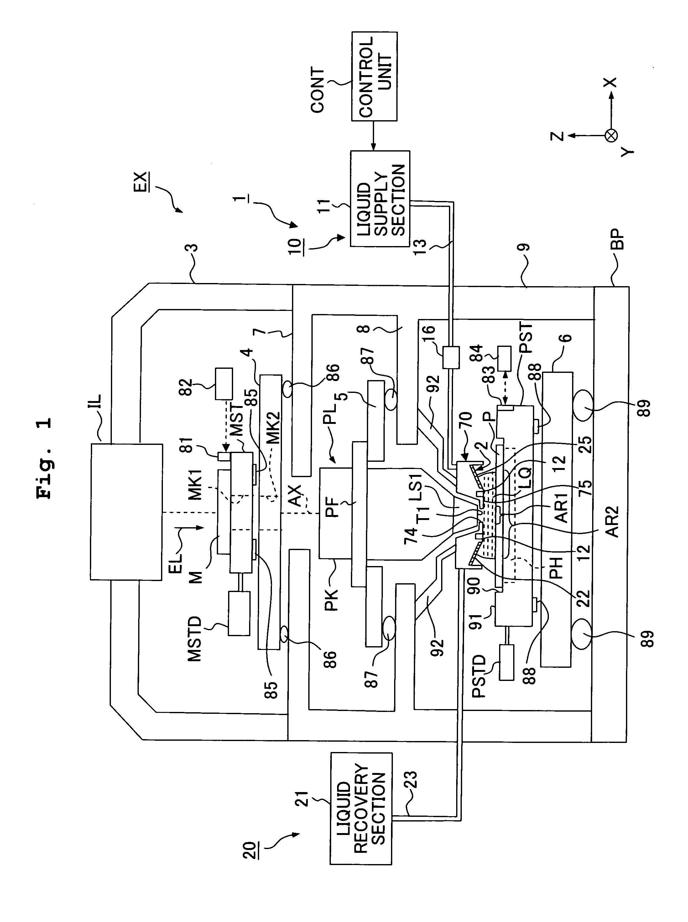
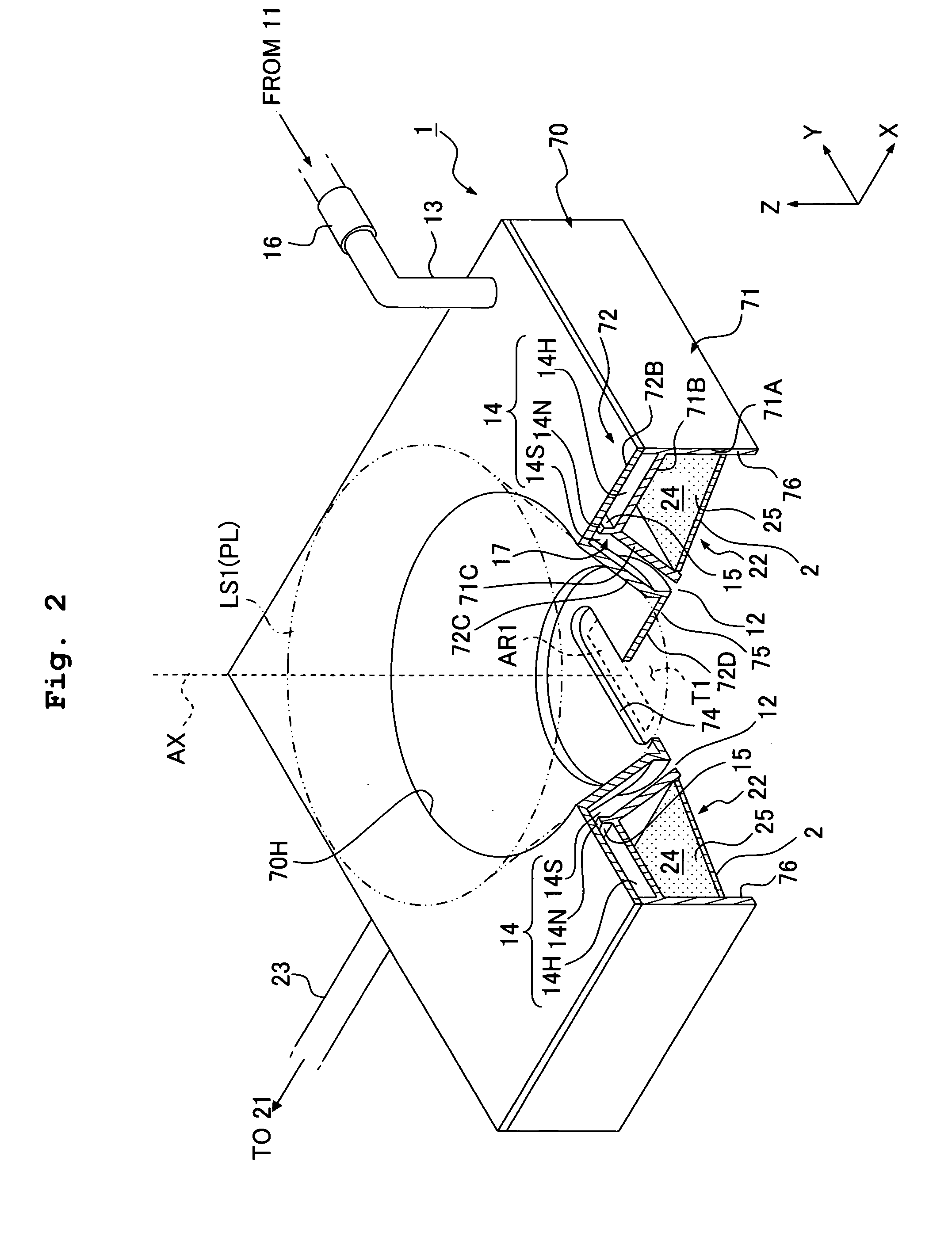
[0058]FIG. 1 shows a schematic arrangement illustrating a first embodiment of the exposure apparatus according to the present invention. With reference to FIG. 1, the exposure apparatus EX includes a mask stage MST which is movable while holding a mask M, a substrate stage PST which is movable while holding a substrate P, an illumination optical system IL which illuminates, with an exposure light beam EL, the mask M held by the mask stage MST, a projection optical system PL which projects an image of a pattern of the mask M illuminated with the exposure light beam EL onto the substrate P held by the substrate stage PST to perform the exposure, and a control unit CONT which integrally controls the operation of the entire exposure apparatus EX.
[0059]The exposure apparatus EX of the embodiment of the present invention is the liquid immersion exposure apparatus in which the liquid immersion method is applied in order that the exposure wavelength is substantially shortened to improve the...
second embodiment
[0127]Next, a second embodiment of the present invention will be explained with reference to FIG. 9. In the following explanation, the constitutive parts, which are the same as or equivalent to those of the embodiment described above, are designated by the same reference numerals, and any explanation of which will be simplified or omitted. In the first embodiment described above, the inclined surface 2 is formed by attaching the thin plate-shaped porous member 25 obliquely with respect to the substrate P. However, as shown in FIG. 9, an inclined surface 2″, for which the distance with respect to the surface of the substrate P is increased at positions separated farther from the optical axis AX of the exposure light beam EL, may be provided on the lower surface of the nozzle member 70, and the liquid recovery port 22 may be formed at a predetermined position (in a predetermined area) of a part of the inclined surface 2″. The porous member 25 may be provided in the liquid recovery por...
third embodiment
[0128]FIG. 10 shows a third embodiment of the present invention. As shown in FIG. 10, a first area 2A, which is included in the lower surface 2 of the porous member 25 and which is disposed near to the optical axis AX, may be formed so that an angle of inclination of the first area 2A with respect to the substrate P is larger than an angle of inclination of a second area 2B with respect to the substrate P, the second area 2B being disposed outside the first area 2A.
PUM
 Abstract
Description
Claims
Application Information
 - R&D
- Intellectual Property
- Life Sciences
- Materials
- Tech Scout
- Unparalleled Data Quality
- Higher Quality Content
- 60% Fewer Hallucinations
Browse by: Latest US Patents, China's latest patents, Technical Efficacy Thesaurus, Application Domain, Technology Topic, Popular Technical Reports.
© 2025 PatSnap. All rights reserved.Legal|Privacy policy|Modern Slavery Act Transparency Statement|Sitemap|About US| Contact US: help@patsnap.com


