Machine tool

a technology of machine tools and tools, applied in the field of machine tools, can solve the problems of affecting the operation of the drive system of the table, the flow of machining fluid (coolant), and the inability of small machine tools to secure an internal space, and achieve the effect of low cos

Inactive Publication Date: 2008-10-30
FANUC LTD
View PDF7 Cites 7 Cited by
  • Summary
  • Abstract
  • Description
  • Claims
  • Application Information

AI Technical Summary

Benefits of technology

[0021]With a simply configuration of providing the inclined groove around the machining region and supplying machining fluid into the groove, chips can be discharged outside the machine and that chip discharge means can be obtained at low cost.

Problems solved by technology

If the deposited chips are left as they are, they may hinder the operations of drive systems for a table, saddle, etc. or retard the flow of machining fluid (coolant).
According to the above method in which the chips are discharged from the machine by means of the chip conveyor or the like, however, the chip conveyor or some other discharge means must be provided only for chip discharge, thus entailing an increase in cost.
Further, there is a problem that a small machine tool cannot secure an internal space in which the conveyor or the like can be set.
In the prior art example shown in FIGS. 2a and 2b, however, the pipes must be set extending up to the front part of the machine in order to run the cutting fluid from the front part, so that the interior of the machine is complicated, and the pipes sometimes may constitute starting points for undesirable chip deposits.

Method used


Image

  • Machine tool
  • Machine tool
  • Machine tool

Examples


Embodiment Construction

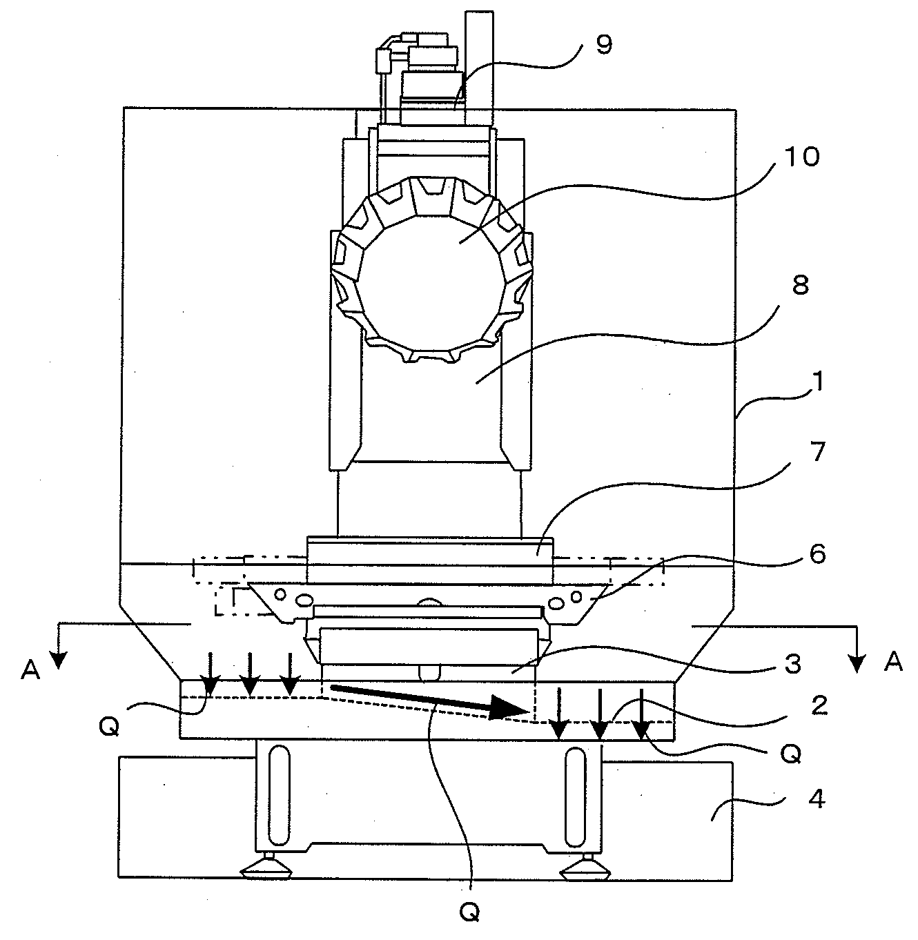
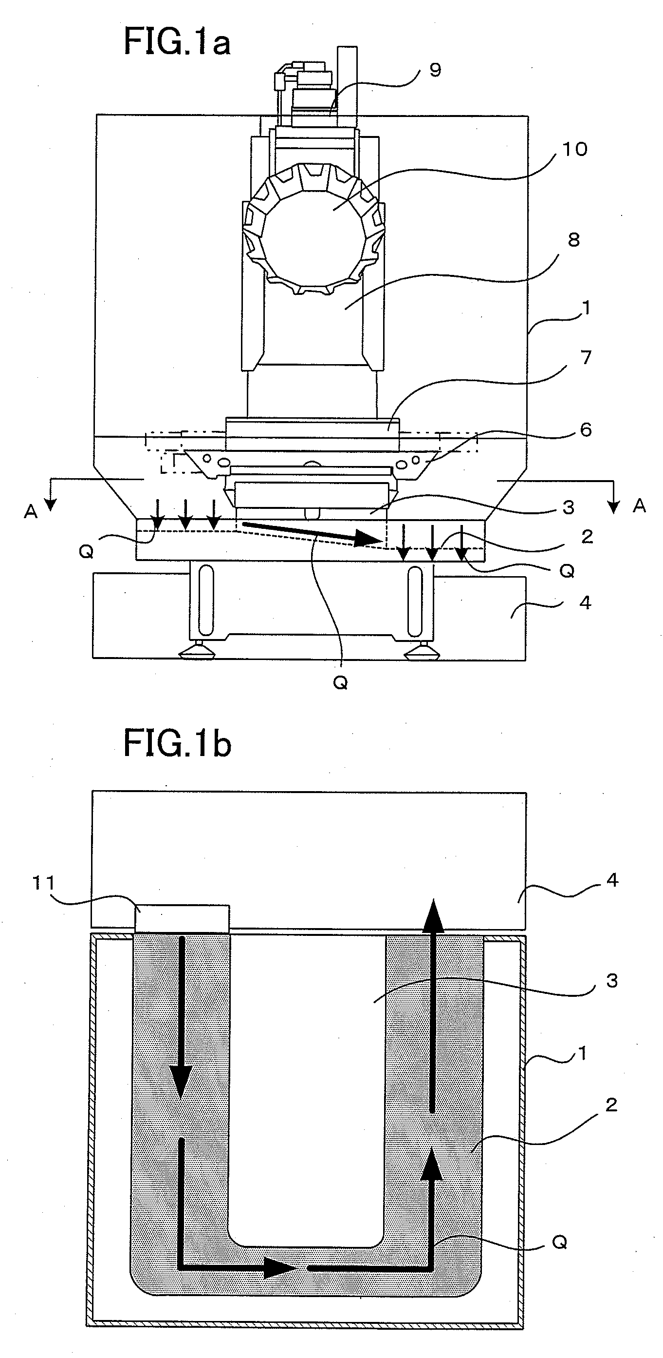
[0024]FIGS. 1a and 1b are schematic views showing one embodiment of the present invention. This embodiment is an example of a machining center. FIG. 1a is a front view, and FIG. 1b is a schematic sectional view taken along line A-A of FIG. 1a without illustration of a guide mechanism, a table, etc.

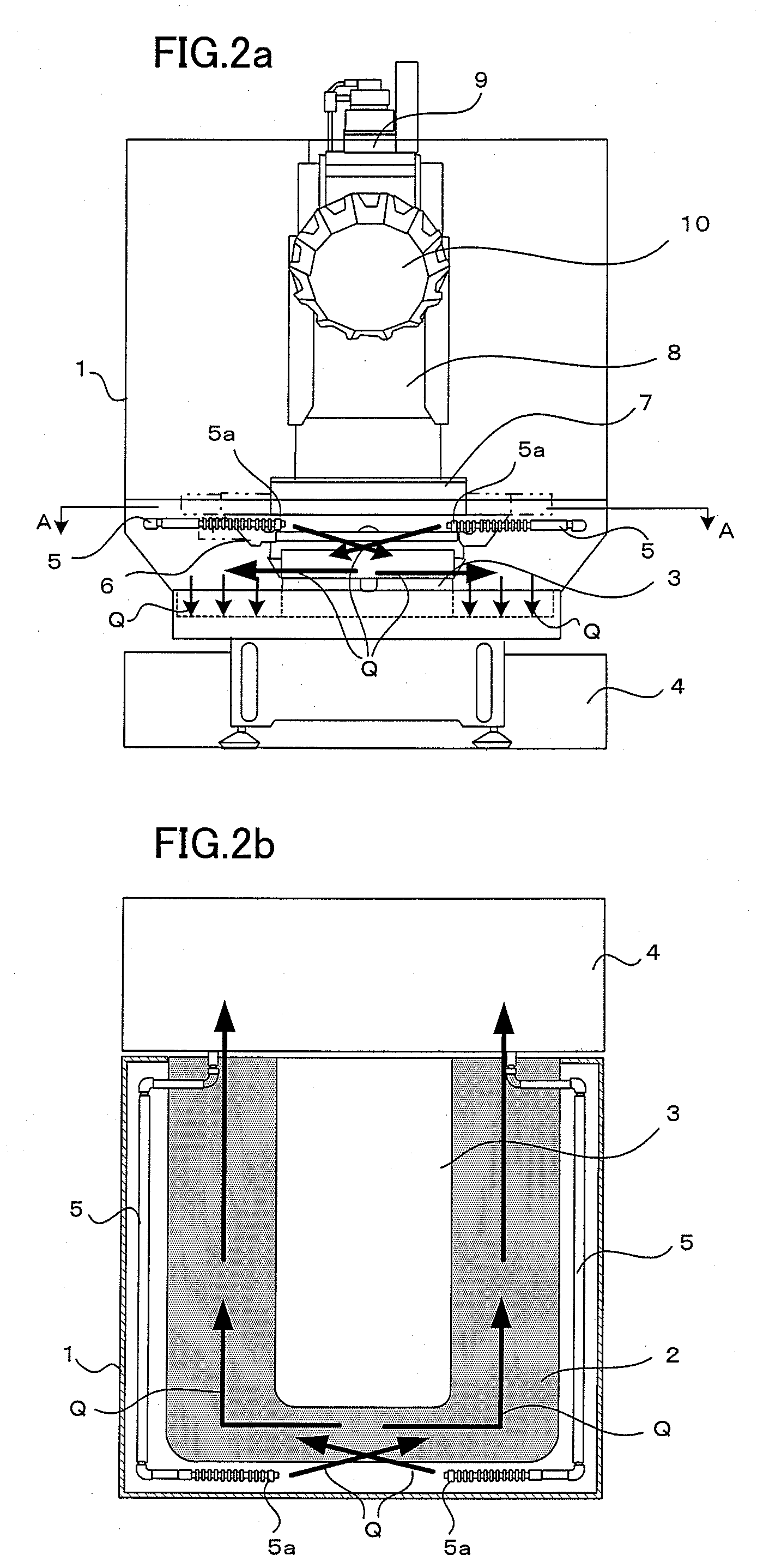
[0025]This embodiment differs from the prior art example shown in FIGS. 2a and 2b in the structure of a groove and the direction in which machining fluid flows in the groove and in that piping for the machining fluid supply to the groove does not extend up to the front part. Like numerals are used to designate common members of this embodiment and the prior art example shown in FIGS. 2a and 2b.

[0026]A table 7 is set on the bed 3 with a guide mechanism 6 between them. A column 8 for supporting a spindle 9 is disposed behind the bed 3. A splash guard 1 is provided covering the front part and two opposite side parts of the bed 3. The splash guard 1 has a bottom portion, from which the bed 3 ...


PUM

PropertyMeasurementUnit
structureaaaaaaaaaa

Abstract

A machine tool capable of removing chips from the machine with a simple structure. A continuous groove is formed at the lowest position of a splash guard surrounding a bed so as to extend from a rear end of the machine along one side portion, a front portion and the other side portion of the bed. Machining fluid brought into the groove from a coolant tank flows along the groove and is recovered into the coolant tank. A bottom of the groove has a continuous slope such that an inlet side where the machining fluid is brought in through the discharge port is highest (or the groove is shallowest) and a discharge side for the coolant tank is lowest (or the groove is deepest). The chips dropped in the groove are discharged together with the machining fluid into the coolant tank where the chips and the machining fluid are separated.

Description

BACKGROUND OF THE INVENTION[0001]1. Field of the Invention[0002]The present invention relates to a machine tool, and more particularly to removal of chips produced in the machine tool by machining a workpiece.[0003]2. Description of the Related Art[0004]In a machine tool, large amounts of chips are produced and deposited inside a splash guard when a workpiece is machined by means of a tool. If the deposited chips are left as they are, they may hinder the operations of drive systems for a table, saddle, etc. or retard the flow of machining fluid (coolant). It is necessary, therefore, to efficiently discharge the chips from the machine lest they deposit, so that various methods are proposed for chip discharge.[0005]Roughly, there are two types of methods for discharging the chips from the machine.[0006]A method in which the chips are discharged from the machine by means of a chip conveyor or the like.[0007]A method in which the chips are discharged from the machine with cutting fluid ...

Claims


Application Information

Patent Timeline
Patent Type & Authority Applications(United States)
IPC IPC(8): B26D7/18
CPCB23Q11/0053B23Q11/0057B23Q11/08Y10T409/30392Y10T409/309576Y10T409/304032Y10T409/304088Y10T407/24Y10T82/16098
Inventor TEZUKA, HIROKISATO, NAOKI
Owner FANUC LTD
Why Eureka
Try Eureka