Combustion equipment and burner combustion method

a combustion method and combustion equipment technology, applied in combustion types, combustion methods, combustion using lumps and pulverulent fuels, etc., can solve the problems of limit to reducing nox emissions and unstable flames, and achieve the effect of reducing nox emissions

Inactive Publication Date: 2008-10-30
HITACHI LTD
View PDF24 Cites 95 Cited by
  • Summary
  • Abstract
  • Description
  • Claims
  • Application Information

AI Technical Summary

Benefits of technology

[0011]The combustion equipment of a coaxial jet combustion scheme according to the present invention can achieve a further reduction in NOx emissions.

Problems solved by technology

However, if the operation is done under a lean fuel condition with a high ratio of air flow to fuel flow, flames become unstable.
Thus, there is a limit to reduction in NOx emissions.

Method used


Image

  • Combustion equipment and burner combustion method
  • Combustion equipment and burner combustion method
  • Combustion equipment and burner combustion method

Examples


embodiment 1

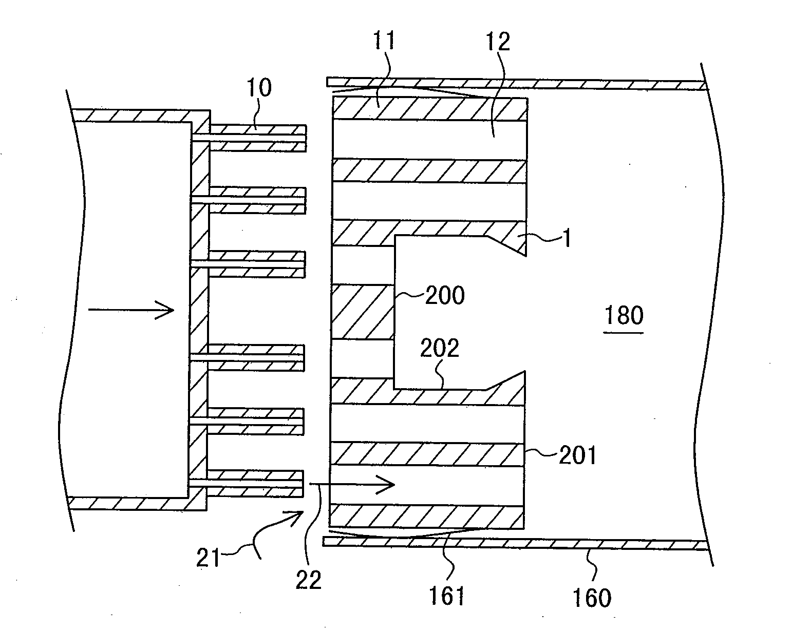
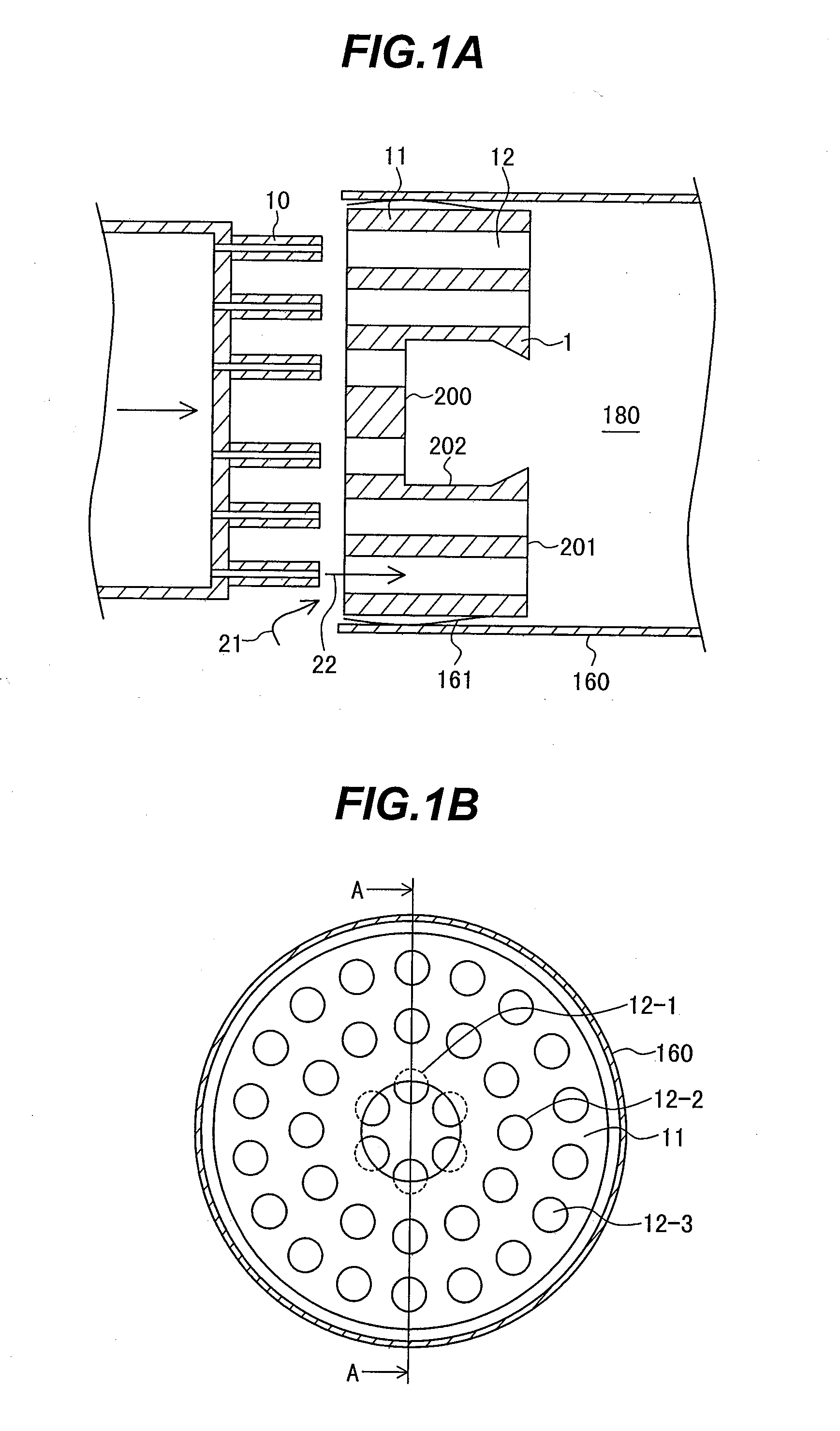
[0058]FIG. 1B is a front view of a burner plate 11 as viewed from a combustion chamber 180. FIG. 1A is an enlarged schematic cross-sectional view taken along line A-A of FIG. 1B, illustrating fuel nozzles 10, air holes 12 and their peripheral portions in the entire gas turbine schematically shown in FIG. 11.

[0059]A burner of the first embodiment includes the fuel nozzles 10; the burner plate 11 having the air holes 12; a protrusion 1 formed on the burner plate 11; and a liner 160 defining the combustion chamber 180. A spring seal 161 is provided between the burner plate 11 and the liner 160.

[0060]Fuel flow 22 is jetted from the fuel nozzle 10 toward the inlet portion of the air hole 12. Air flow 21 enters the inlet portion of the air hole 12 from the outer circumferential side of the fuel nozzle 10. The air flow 21 having entered the air holes 12 passes through the inside of the air hole 12 so as to encircle the fuel flow 22 from the outer circumferential side thereof, and jet out f...

embodiment 2

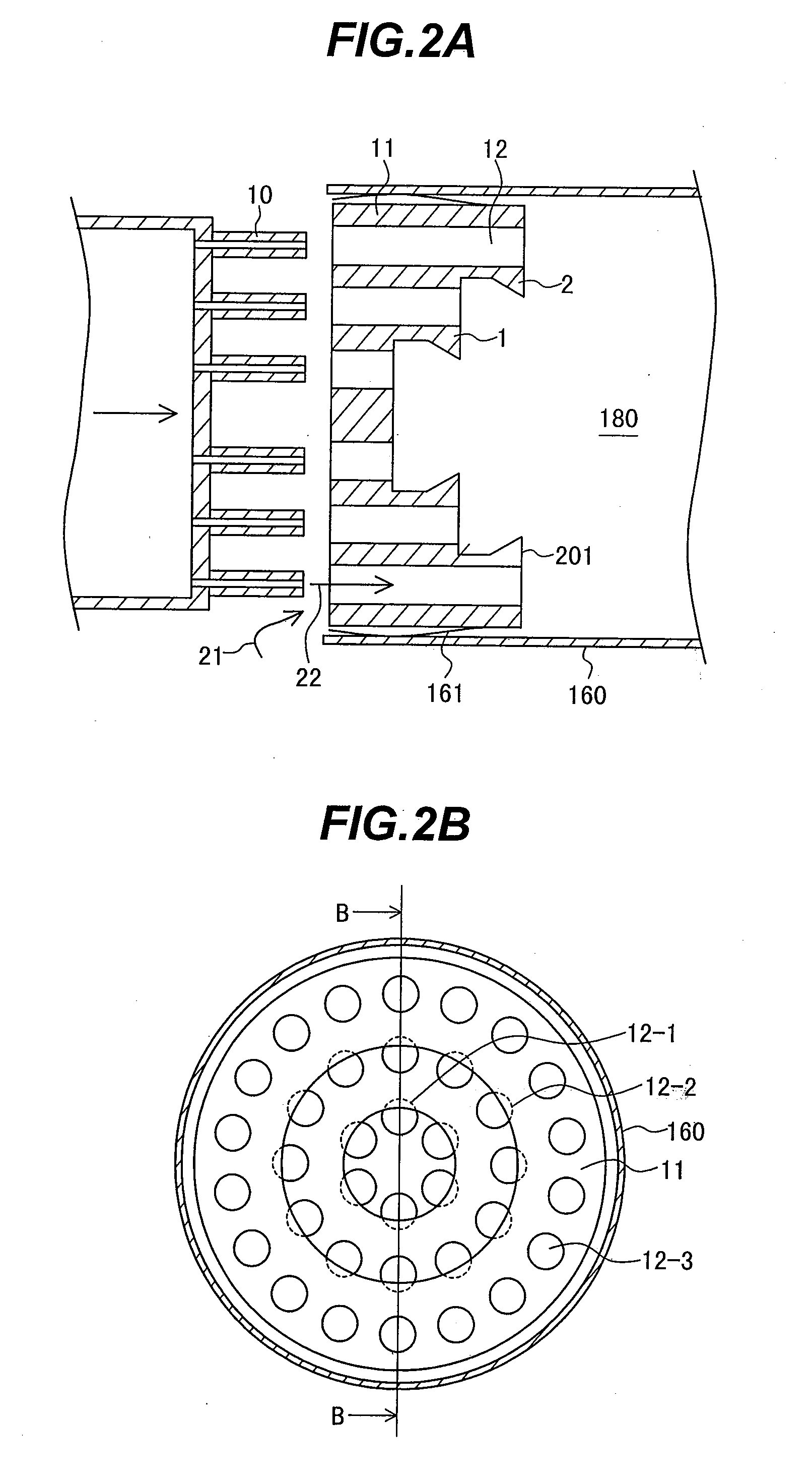
[0078]FIG. 2B is a front view illustrating a burner plate 11 as viewed from a combustion chamber 180. FIG. 2A is an enlarged schematic cross-sectional view illustrating fuel nozzles 10, air holes 12 and their peripheral portions in the entire gas turbine of FIG. 11, taken along line B-B of FIG. 2B.

[0079]In the first embodiment, the flames formed by the first circular row air holes 12-1 are stabilized to thereby improve the stability of the flames formed by the second and third circular row air holes 12-2, 12-3. In contrast to this, in a second embodiment, a protrusion 2 is provided for also the second circular row air holes 12-2 to improve the stability of the flames formed by the second circular row air holes 12-2. Consequently, the flame stability of the entire burner can be further enhanced.

[0080]The basic mechanism of the flame stability improvement is similar to the contents described with FIG. 7. Specifically, high-temperature recirculation flow is formed not only on the burne...

embodiment 3

[0084]FIG. 3B is a front view illustrating a burner plate 11 as viewed from a combustion chamber 180. FIG. 3A is an enlarged schematic cross-sectional view illustrating fuel nozzles 10, air holes 12 and their peripheral portions in the entire gas turbine, taken along line C-C of FIG. 3B. FIG. 12 illustrates a shape of the air hole 12.

[0085]The burner plate 11 in a third embodiment is shaped such that a circular cone is hollowed out. In other words, a plane of the burner plate 11 at which an outlet portion 301 of the air hole 12 is located is shaped to open toward the combustion chamber as shown in FIG. 12. Specifically, the plane formed by the outlet portion 301 of the air hole 12 is inclined with respect to the central axis of the burner.

[0086]An obstacle is provided on the downstream side of the outlet portion 301 of the air hole 12 so as to disturb fuel flow and air flow. This obstacle corresponds to the protrusion 1, which is formed annular and provided for each circular row air...


PUM


Abstract

Combustion equipment of a coaxial jet combustion scheme is provided that includes: a burner plate in which fuel and air are mixed with each other while the fuel and air pass through an air hole; a burner plate extension which is a portion of the burner plate and extends toward a combustion chamber side spaced apart from the air hole; and a protrusion disposed on the combustion chamber side of the burner plate extension so as to protrude in a direction where flow of the fuel moves. In the combustion equipment, a gap between opposite portions of the protrusion is greater than a diameter of the air hole and a flame source forming area is defined between the burner plate, the burner plate extension and the protrusion. The combustion equipment of a coaxial jet combustion scheme can achieve a further reduction in NOx emissions.

Description

Background of the Invention[0001]1. Field of the Invention[0002]The present invention relates to combustion equipment and to a burner combustion method.[0003]2. Description of the Related Art[0004]Regulations on the emissions of air pollutants have been stringent in the recent years. For gas turbine combustors, for instance, various combustion schemes are under research to reduce the emission levels of nitrogen oxide (NOx) contained in exhaust gases.[0005]One of these combustion schemes is a coaxial jet combustion scheme in which each of fuel nozzles and a corresponding one of air holes are arranged coaxially with each other and fuel and air are supplied to and burned in a combustion chamber. The coaxial jet combustion scheme can promote the mixing of fuel with air in a very short distance as compared with the conventional premixed combustion scheme so that it can reduce NOx emissions. See e.g. JP-A-2003-148734.SUMMARY OF THE INVENTION[0006]Combustion equipment of the coaxial jet co...

Claims


Application Information

Patent Timeline
Patent Type & Authority Applications(United States)
IPC IPC(8): F23C5/00
CPCF23R3/286F23R2900/00015F23R2900/03343
Inventor SAITO, TAKEOMIURA, KEISUKEKOYAMA, KAZUHITOINOUE, HIROSHI
Owner HITACHI LTD
Why Eureka
Try Eureka