Osmotically Driven Dispense Pump and Related Components for Use in High Pressure Applications

Active Publication Date: 2008-10-30
UNIV OF UTAH RES FOUND
View PDF30 Cites 28 Cited by
  • Summary
  • Abstract
  • Description
  • Claims
  • Application Information

AI Technical Summary

Benefits of technology

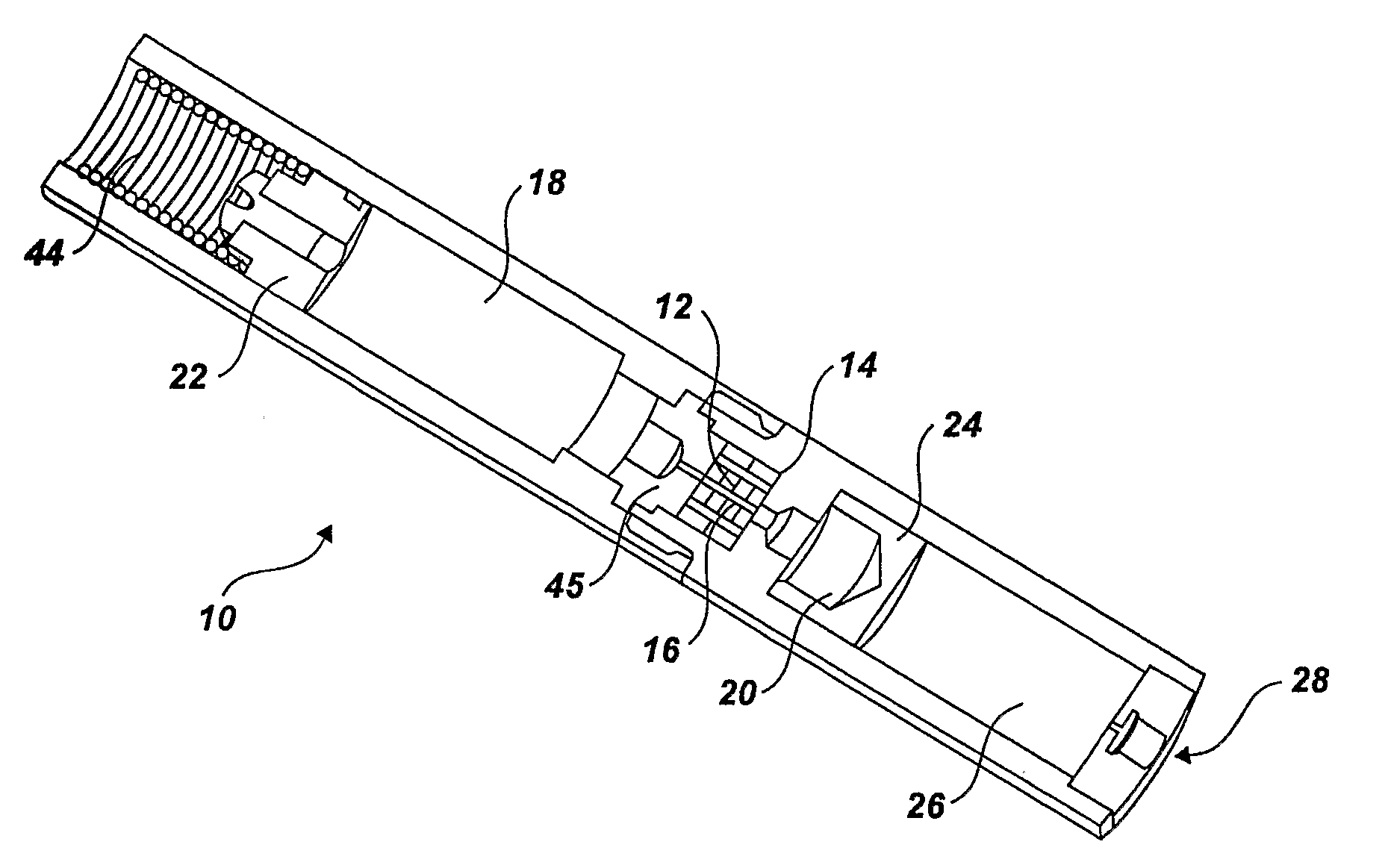
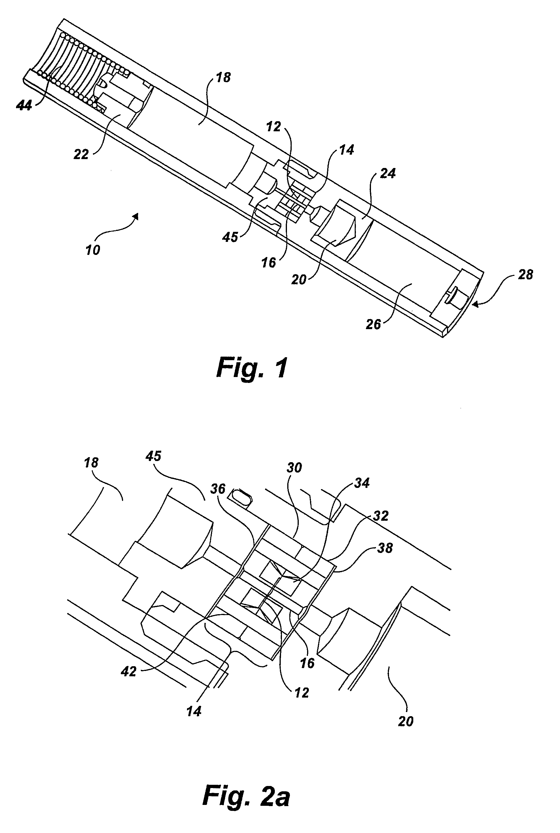
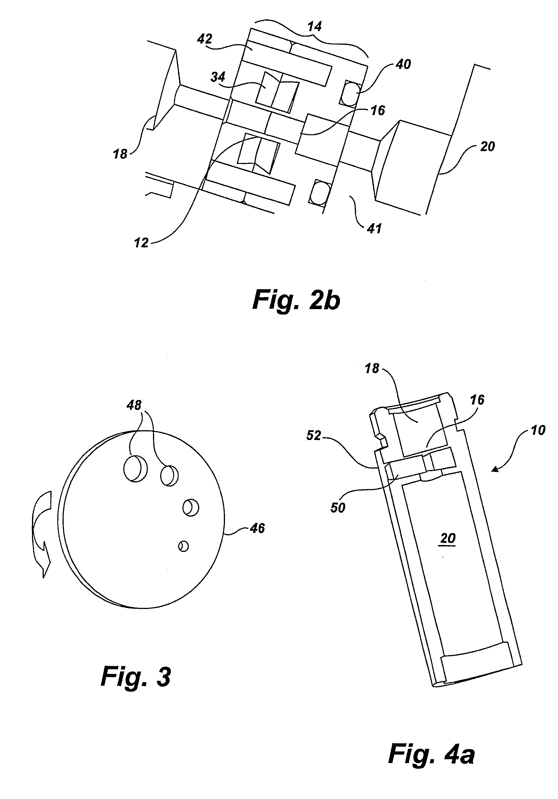
[0006]Accordingly, the present invention provides a high pressure osmotic dispense pump having a substantially continuous delivery rate and extended delivery times. The dispense pump can include a semi-permeable membrane which is substantially free of distortions and lateral stretching stresses. Generally, the dispense pump of the present invention operates using an osmotic process driven by a concentration gradient of solvent across a selectively permeable membrane. A solvent reservoir and a solution reservoir can be fluidly connected on either side of the semi-permeable membrane. The reservoir chambers can be formed to include pistons which can move to accommodate changes in volumes as the solvent diffuses across the membrane. The membrane housing and configuration of the present invention allows for consistent and accurate flow rates at the micro-liter level and improved control of the surface area of the semi-permeable membrane.

Problems solved by technology

Unfortunately, these pumps tend to have limited control over the flow rate.
Specifically, the flexible housings and membranes can create fluctuations in flow rate which are unpredictable.
Although this may be acceptable in some applications, fluctuations in flow rate can generally be unacceptable for applications requiring more precise flow rates.
Furthermore, continuous precise delivery of fluids for extended periods of time can present a unique challenge to these types of devices.
Most often, current technologies are limited to delivery times of several weeks to a couple of months.
If used in a patient, this requires frequent replacement and can be inconvenient.
Further, such short useful durations increase costs associated with replacement, maintenance, and materials.

Method used


Image

  • Osmotically Driven Dispense Pump and Related Components for Use in High Pressure Applications
  • Osmotically Driven Dispense Pump and Related Components for Use in High Pressure Applications
  • Osmotically Driven Dispense Pump and Related Components for Use in High Pressure Applications

Examples


examples

[0084]The following are examples which illustrate various osmotic dispense pumps, methods of forming the pumps and methods of dispensing fluid using the pumps in accordance with the present invention. However, it is to be understood that the following are only exemplary or illustrative of the application of the principles of the present invention. Numerous modifications and alternative compositions, methods, and systems can be devised by those skilled in the art without departing from the spirit and scope of the present invention. The appended claims are intended to cover such modifications and arrangements. Thus, while the present invention has been described above with particularity, the following Examples provide further detail in connection with several specific embodiments of the invention.

[0085]Device Design and Testing Conditions

[0086]Among the following examples, two different semi-permeable materials are utilized, polyimide and porous glass. The devices using polyimide as t...


PUM


Abstract

A high pressure osmotic dispense pump (10) having a substantially continuous delivery rate and extended delivery times is described and disclosed. The dispense pump (10) includes a semi-permeable membrane (12) which is substantially free of distortions and lateral stretching stresses. The membrane housing (14) and configuration of the present invention allows for consistent and accurate flow rates at the micro-liter level and improved control of the surface area of the semi-permeable membrane (12). This osmotic pump (10) also includes optional methods for activating and deactivating the osmotic process and / or controlling flow rates. Along with these features, the pump can be amplified or modulated to increase the dispense rate and / or adjust the flow rate during operation.

Description

RELATED APPLICATIONS[0001]This application claims the benefit of earlier filed U.S. Provisional Patent Application No. 60 / 702,028, filed Jul. 22, 2005, which is incorporated by reference herein in its entirety.FIELD OF THE INVENTION[0002]The present invention relates to osmotically driven pumps. Accordingly, the present invention involves the fields of chemistry, physics, micromechanical devices, engineering, and materials science.BACKGROUND OF THE INVENTION[0003]Devices suitable for delivering very small volumes of fluid have been available for several decades. Osmotic pumps are of particular interest for delivering small amounts of drugs or other similar applications. These osmotic pumps typically utilize a driving force based on a concentration gradient across a semi-permeable membrane. Most current designs involve a variety of flexible housings and may include one or more chambers. Unfortunately, these pumps tend to have limited control over the flow rate. Specifically, the flex...

Claims


Application Information

Patent Timeline
IPC IPC(8): A61K9/22
CPCF04B17/00A61K9/0004A61M5/145A61M2005/14513
Inventor DEEM, TRENTLIGRANI, PHILHANSEN, BRADLEY C.
Owner UNIV OF UTAH RES FOUND
Why Eureka
Try Eureka