Dosing Limitation for an Implantable Medical Device

a medical device and limitation technology, applied in the field of medical devices, can solve the problems of reducing the efficacy of neurostimulation by imd, affecting the safety and efficacy of neurostimulation, and affecting the safety of neurostimulation,

Active Publication Date: 2008-10-30
LIVANOVA USA INC
View PDF99 Cites 21 Cited by
  • Summary
  • Abstract
  • Description
  • Claims
  • Application Information

AI Technical Summary

Problems solved by technology

One problem associated with the state of the art is that optimal safety and efficacy of neurostimulation by an IMD may be compromised by allowing a patient to initiate neurostimulation ad libitum.
For example, excessive delivery of electrical current to a neurological structure may result in a net electrical charge on, and subsequent damage to, the target neurological structure.
Current doses that do not lead to tissue damage may lead to discomfort.
Also, extra dosing may lead to reduced efficacy by interfering with short-term or long-term recovery periods necessary or advisable for proper and / or safe neural functioning.
Further, battery life can be shortened by excessive dosing.
On the other hand, blanket prohibition of patient-initiated neurostimulation may lead to ineffective alleviation of symptoms during acute crisis, when extra dosing may be helpful, e.g., during an epileptic seizure suffered by a patient having an implanted vagus nerve stimulation (VNS) device.

Method used


Image

  • Dosing Limitation for an Implantable Medical Device
  • Dosing Limitation for an Implantable Medical Device
  • Dosing Limitation for an Implantable Medical Device

Examples


Embodiment Construction

[0019]Illustrative embodiments of the invention are described herein. In the interest of clarity, not all features of an actual implementation are described in this specification. In the development of any such actual embodiment, numerous implementation-specific decisions must be made to achieve the design-specific goals, which will vary from one implementation to another. It will be appreciated that such a development effort, while possibly complex and time-consuming, would nevertheless be a routine undertaking for persons of ordinary skill in the art having the benefit of this disclosure.

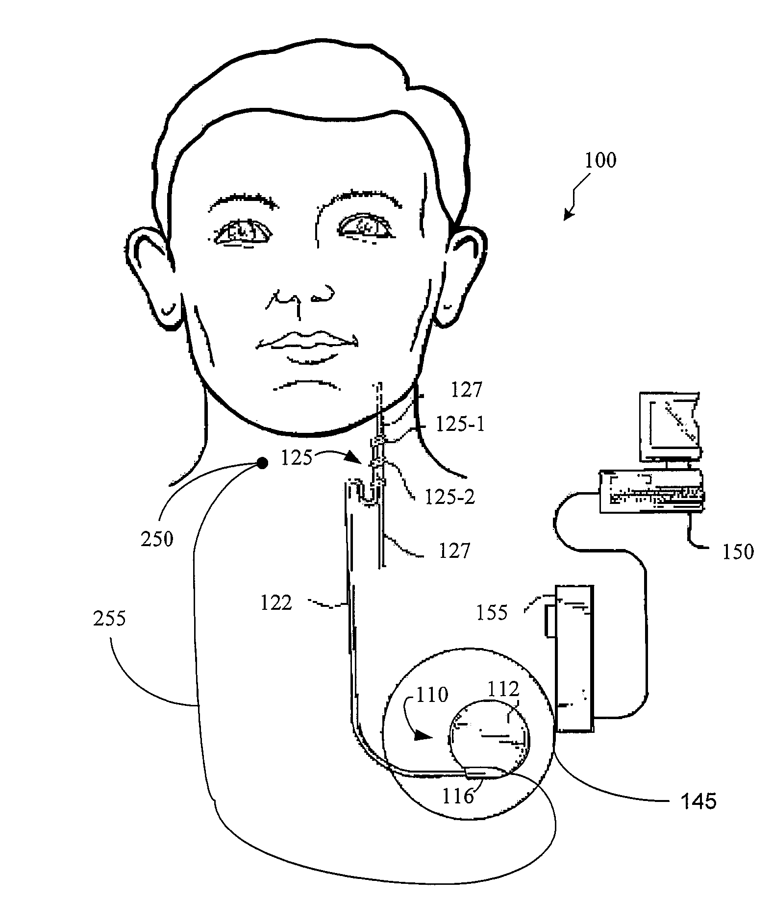
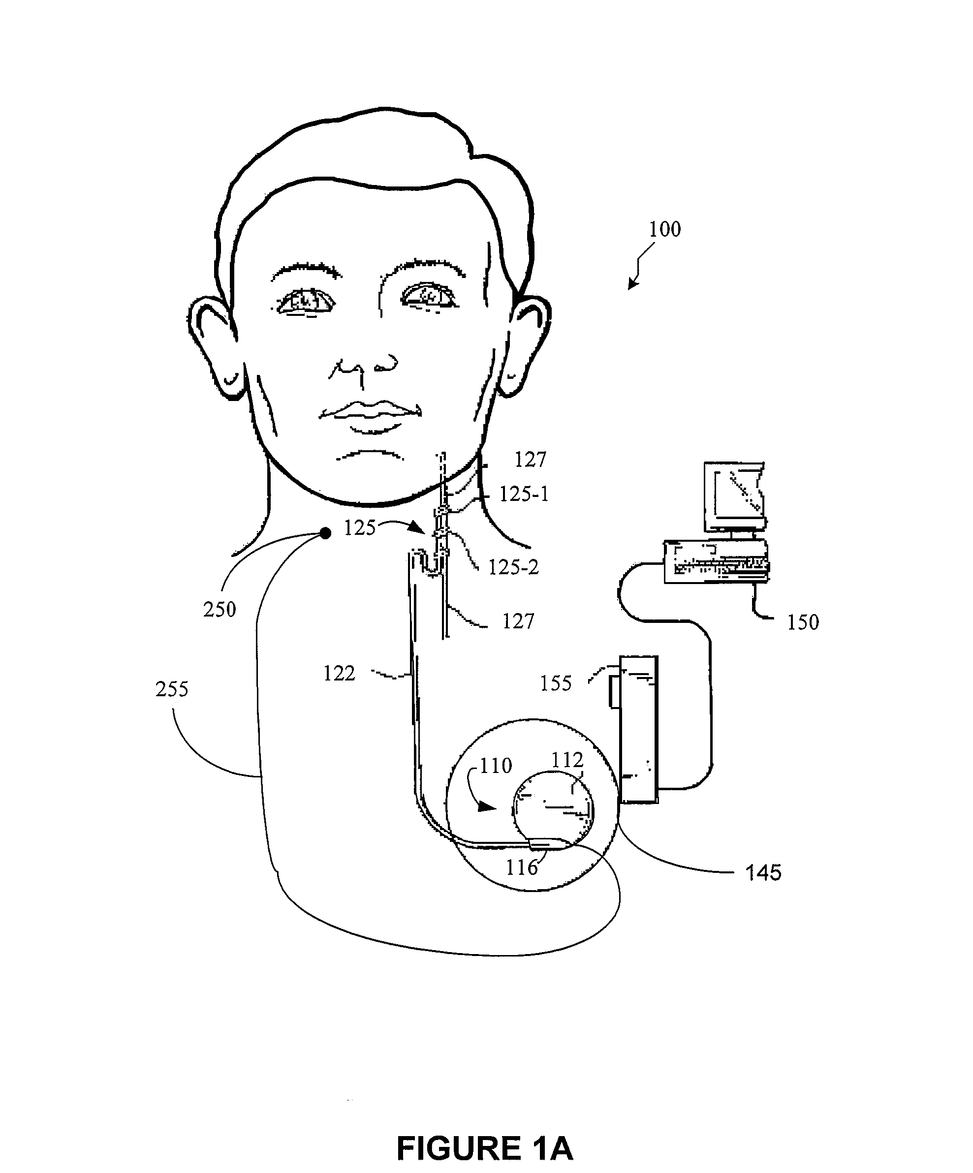
[0020]Embodiments of the present invention provide for an input to the IMD that would prompt the IMD to operate in an alternative mode for a predetermined time period, or until another triggering input is received. The alternative mode may provide for prompting an alternative operation of the IMD, by which is meant a mode other than a primary mode. A primary mode is a preprogrammed mode in which t...


PUM


Abstract

A method for limiting patient-initiated electrical signal therapy provided by an implantable medical device (IMD) to a cranial nerve of a patient. At least one electrical signal therapy limit selected from the group consisting of a maximum number of patient-initiated signals to provide a therapeutic electrical signal per a time period, a maximum dose of the therapeutic electrical signal per a time period, a maximum duration of the therapeutic electrical signal per a time period, a maximum rate of change of the number of patient-initiated signals to provide a therapeutic electrical signal per a time period, a maximum rate of change of the dose of the therapeutic electrical signal per a time period, and a maximum rate of change of the duration of the electrical signal therapy per a time period is specified. A patient-initiated signal to begin a therapeutic electrical signal is received. Whether or not said electrical signal therapy limit is exceeded by said step of detecting a patient-initiated signal is determined. An action in response to said step of determining whether or not said limit is exceeded is performed, said action selected from the group consisting of providing a first electrical signal therapy to said cranial nerve, providing a second, reduced electrical signal therapy to said cranial nerve, providing a third, enhanced electrical signal therapy to said cranial nerve, inhibiting an electrical signal therapy to said cranial nerve, providing a background electrical signal to said cranial nerve, and inhibiting a background electrical signal to said cranial nerve.

Description

BACKGROUND OF THE INVENTION[0001]1. Field of the Invention[0002]This invention relates generally to medical devices, and, more particularly, to methods, apparatus, and systems for limiting patient-initiated electrical signal therapy by a medical device.[0003]2. Description of the Related Art[0004]There have been many improvements over the last several decades in medical treatments for disorders of the nervous system, such as epilepsy and other motor disorders, and abnormal neural discharge disorders. One of the more recently available treatments involves the application of an electrical signal to reduce various symptoms or effects caused by such neural disorders. For example, electrical signals have been successfully applied at strategic locations in the human body to provide various benefits, including reducing occurrences of seizures and / or improving or ameliorating other conditions. A particular example of such a treatment regimen involves applying an electrical signal to the vag...

Claims


Application Information

Patent Timeline
Patent Type & Authority Applications(United States)
IPC IPC(8): A61N1/08
CPCA61N1/36082A61N1/37235A61N1/36164
Inventor ARMSTRONG, RANDOLPH K.
Owner LIVANOVA USA INC
Why Eureka
Try Eureka