Electronic apparatus and image forming apparatus

a technology of image forming apparatus and electronic equipment, which is applied in the direction of power supply for data processing, instruments, measurement devices, etc., can solve the problems of high uncertainty as to when and how long the secondary battery can be charged, operation of the interface becomes disabled, and load is exerted

Active Publication Date: 2013-06-06
KONICA MINOLTA BUSINESS TECH INC
View PDF5 Cites 9 Cited by
  • Summary
  • Abstract
  • Description
  • Claims
  • Application Information

AI Technical Summary

Benefits of technology

[0014]In specific, the present invention provides, as one aspect thereof, an electronic apparatus comprising: a main body that includes a reception unit and a processing unit, the reception unit receiving a processing request and the processing unit executing processing corresponding to the processing request; and a power supply device that is connected with an external power source and a secondary battery and that includes: a state switching unit that causes the power supply device to switch between a standby state for supplying power from the secondary battery to the reception unit without supplying power from the external power source to the main body and an operation state for supplying power from the external power source to the main body, the state switching unit causing the power supply device to switch between the standby state and the operation state such that, when a processing request is received by the reception unit while in the standby state, the state switching unit causes the power supply device to switch to the operation state, and subsequently, when execution of processing corresponding to the processing request is completed by the processing unit, the state switching unit causes the power supply device to return to the standby state; a charge unit that charges the secondary battery with power from the external power source; and a control unit that controls the charge unit such that, the charge unit is caused to commence charging of the secondary battery during the operation state, and the charge unit is caused to terminate charging of the secondary battery (i) when a value indicative of a present battery power level of the secondary battery reaches a threshold value denoted by Vt and (ii) when the power supply device returns to the standby state before the indicative value reaches Vt, wherein Vt satisfies (VL+Vs)≦Vt<VH, where VL denotes a discharge lower limit of a battery power level of the secondary battery, Vs denotes a decrease in the battery power level of the secondary battery occurring when power from the secondary battery is supplied to the reception unit for an estimated maximum duration of the standby state within a time period having a unit time length, and VH denotes a charge upper limit of the battery power level of the secondary battery.
[0015]The present invention provides, as another aspect thereof, an image forming apparatus comprising: a main body that includes a reception unit and an image forming unit, the reception unit receiving an image forming request and the image forming unit executing image forming corresponding to the image forming request; and a power supply device that is connected with an external power source and a secondary battery and that includes: a state switching unit that causes the power supply device to switch between a standby state for supplying power from the secondary battery to the reception unit without supplying power from the external power source to the main body and an operation state for supplying power from the external power source to the main body, the state switching unit causing the power supply device to switch between the standby state and the operation state such that, when an image forming request is received by the reception unit while in the standby state, the state switching unit causes the power supply device to switch to the operation state, and subsequently, when execution of image forming corresponding to the image forming request is completed by the image forming unit, the state switching unit causes the power supply device to return to the standby state; a charge unit that charges the secondary battery with power from the external power source; and a control unit that controls the charge unit such that, the charge unit is caused to commence charging of the secondary battery during the operation state, and the charge unit is caused to terminate charging of the secondary battery (i) when a value indicative of a present battery power level of the secondary battery reaches a threshold value denoted by Vt and (ii) when the power supply device returns to the standby state before the indicative value reaches Vt, wherein Vt satisfies (VL+Vs)≦Vt<VH, where VL denotes a discharge lower limit of a battery power level of the secondary battery, Vs denotes a decrease in the battery power level of the secondary battery occurring when power from the secondary battery is supplied to the reception unit for an estimated maximum duration of the standby state within a time period having a unit time length, and VH denotes a charge upper limit of the battery power level of the secondary battery.

Problems solved by technology

As such, it is highly uncertain as to when and how long the secondary battery can be charged since the frequency at which user instructions are received differs depending on the time of the day.
When, as mentioned above, it is highly uncertain as to when and how long the secondary battery can be charged, problematic situations may arise such as where the operation of the interface becomes disabled during the standby state due to the battery power level of the secondary battery decreasing as a result of the standby state continuing over a long period of time.
However, although it is highly uncertain as to when and how long the secondary battery can be charged as discussed above, when the secondary battery is charged to the full battery capacity so as to prevent such problematic situations as mentioned above from arising, another problem is brought about.
That is, when the secondary battery is charged to its full battery capacity, a great load is exerted on the secondary battery, and accordingly, the life-span of the secondary battery is shortened.
This problem is not unique to image forming apparatuses having the above described structure, and there is a possibility of the same problem occurring in electronic apparatuses in general.

Method used


Image

  • Electronic apparatus and image forming apparatus
  • Electronic apparatus and image forming apparatus
  • Electronic apparatus and image forming apparatus

Examples


embodiment 1

(1) Structure of Image Forming Apparatus

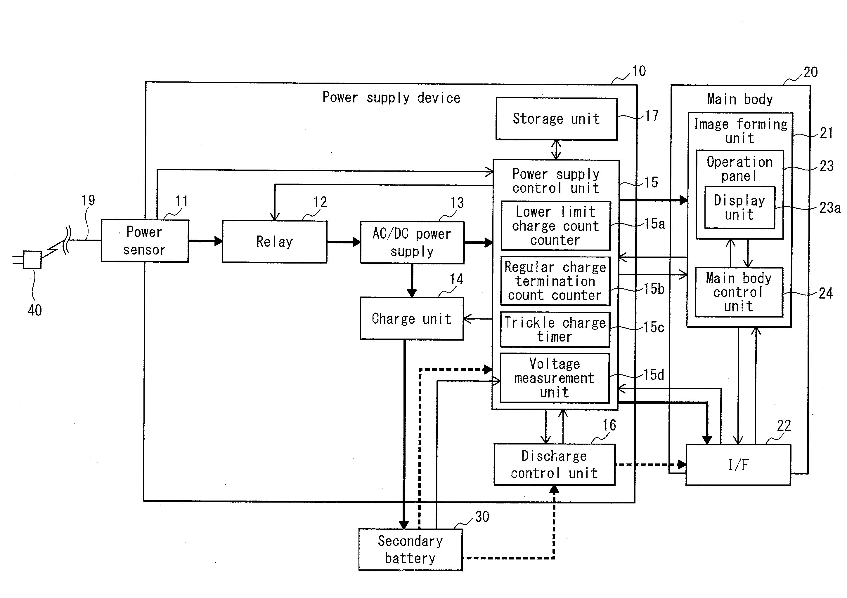
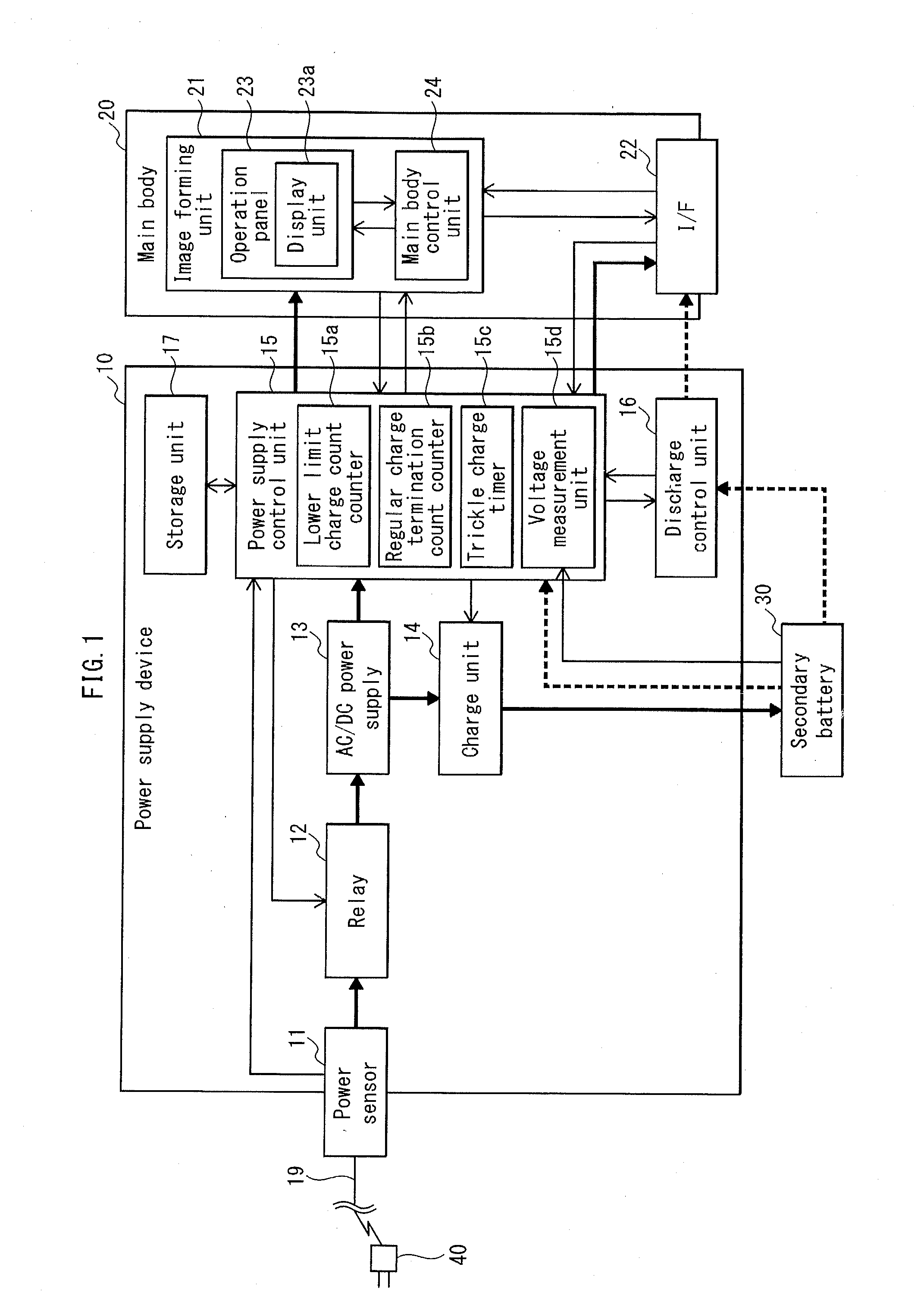
[0036]FIG. 1 is a block diagram describing a structure of an image forming apparatus in embodiment 1. The image forming apparatus is an MFP (Multiple Function Peripheral), which is capable of executing image forming jobs such as printing.

[0037]The image forming apparatus includes a power supply device 10 and a main body 20, as illustrated in FIG. 1.

[0038]The main body 20 includes an image forming unit (a processing unit) 21 and an external interface (an I / F; a reception unit) 22. The image forming unit 21 executes an image forming job of forming an image on a recording sheet based on image data. The I / F 22 is connected to a network (undepicted) such as a LAN and receives an instruction (a processing request) for executing an image forming job from an external terminal device, such as a personal computer, via the network.

[0039]The image forming unit 21 includes an operation panel 23 and a main body control unit 24, and executes image forming in...

embodiment 2

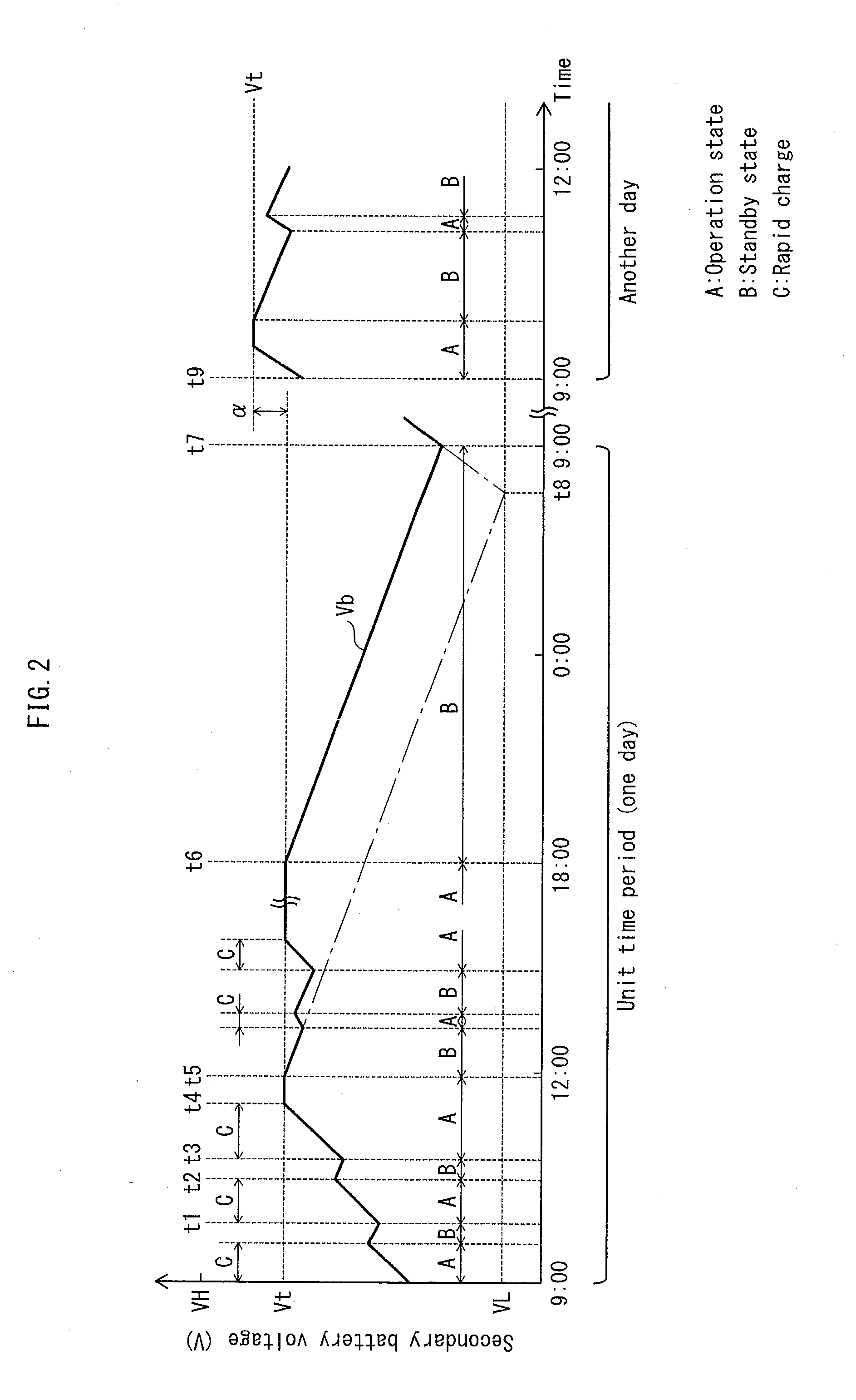
[0196]In embodiment 1, description has been provided of a structure where the estimated maximum duration Ta (e.g., 23 hours) of the standby state is determined in advance, and the charge completion value Vt is set according to the estimated maximum duration Ta. The present embodiment differs from embodiment 1 in that actual measurement is performed of the duration of the standby state within a given day, and the charge completion value Vt for a day following the given day is set according to the duration of the standby state within the previous day. Note that, in the description provided in the following, so as to avoid the same description as provided in embodiment 1 from being repeated once again, description is omitted in the following of aspects similar to those in embodiment 1, and further, components that commonly appear in both embodiments 1 and 2 are provided with the same reference signs.

[0197]FIG. 14 is a diagram describing charge / discharge processing performed with respec...


PUM


Abstract

An electronic apparatus comprising: a main body including a reception unit and a processing unit; and a power supply device switches between an operation state for supplying power from an external power source to the main body and a standby state for supplying power from a secondary battery to the reception unit without supplying power from the power source to the main body. Charging of the battery with power from the power source is performed during the operation state and is terminated when a value indicating power level of the battery reaches a threshold value Vt satisfying (discharge lower limit VL+Vs)≦Vt<charge upper limit VH, Vs denoting a decrease in power level occurring when power from the battery is supplied to the reception unit for an estimated maximum duration of the standby state within a time period having a unit time length.

Description

CROSS-REFERENCE TO RELATED APPLICATIONS[0001]This application is based on application No. 2011-265086 filed in Japan, the contents of which are hereby incorporated by reference.BACKGROUND OF THE INVENTION[0002](1) Field of the Invention[0003]The present invention relates to an electronic apparatus to be provided with a secondary battery and an image forming apparatus to be provided with a secondary battery.[0004](2) Description of the Related Art[0005]Electronic apparatuses of various types operate on both power supplied from a commercial power source (an external power source) and power supplied from a secondary battery, such as a nickel-metal hydride battery.[0006]For instance, an image forming apparatus, which is one type of an electronic apparatus, may be provided with an image forming unit (a processing unit) that executes image forming and an interface (a reception unit) that receives an instruction for image forming issued from outside the image forming apparatus. Convention ...

Claims


Application Information

Patent Timeline
Patent Type & Authority Applications(United States)
IPC IPC(8): G06F1/26
CPCG06F1/263
Inventor TATSUMOTO, YUHEIHASEBE, TAKASHITAMURA, TOMONOBUTANIMURA, YASUTAKAEGUCHI, HIROSHIHIRAGUCHI, HIROSHI
Owner KONICA MINOLTA BUSINESS TECH INC
Why Eureka
Try Eureka