Silencer tube with internal stepped profile

Inactive Publication Date: 2008-11-06
JJE BRANDS LLC
View PDF18 Cites 22 Cited by
  • Summary
  • Abstract
  • Description
  • Claims
  • Application Information

AI Technical Summary

Benefits of technology

[0011]The present invention provides an apparatus and method for easily, and quickly disassembling a noise suppressor, specifically for removing the core from the tube of the noise suppressor. The apparatus features a tapered tube with a stepped profile and a baffle core (list robert patent application) which is machined to

Problems solved by technology

When the core is seated within the tube carbon and lead will be limited in t

Method used


Image

  • Silencer tube with internal stepped profile
  • Silencer tube with internal stepped profile
  • Silencer tube with internal stepped profile

Examples


Example

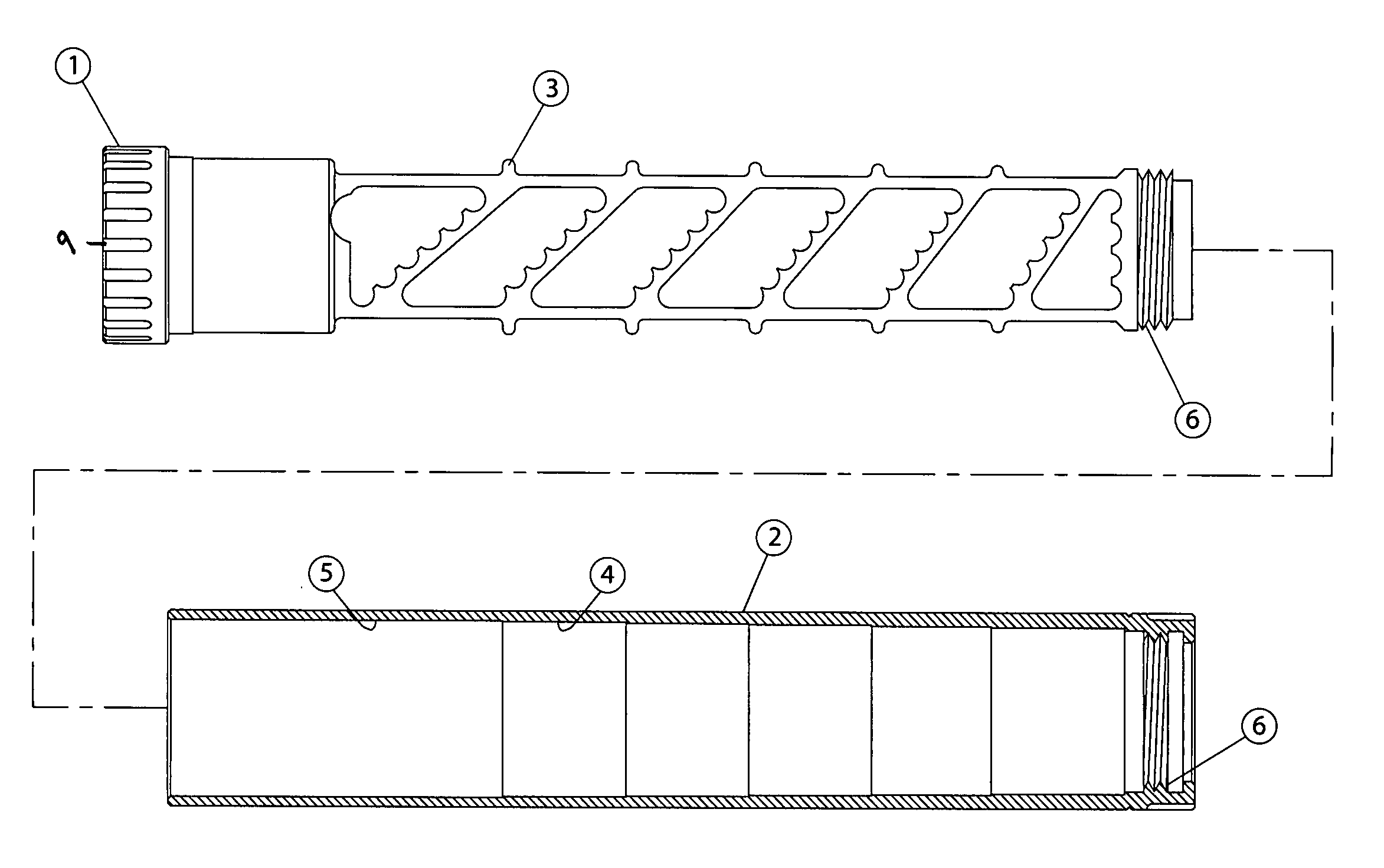
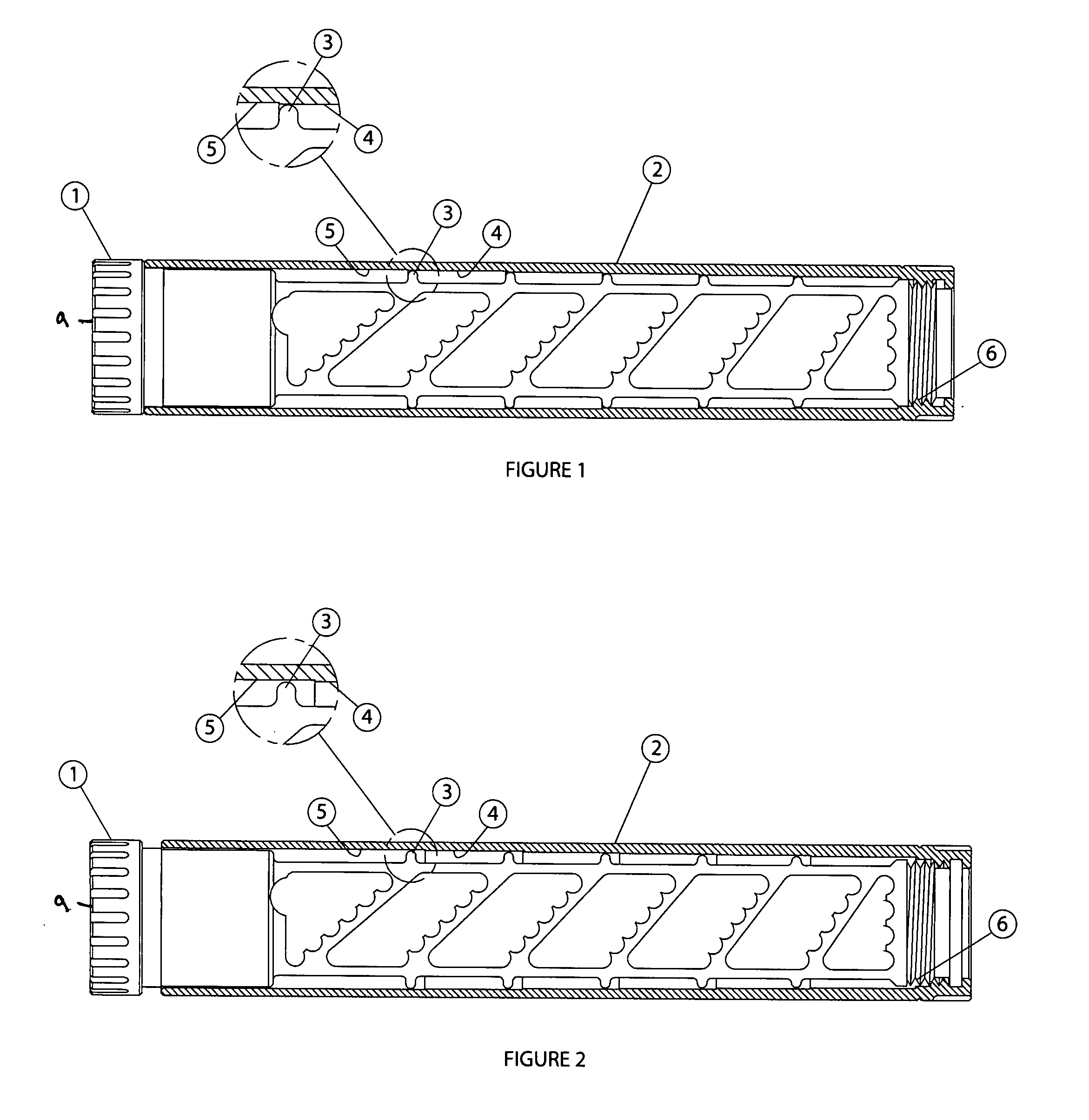
[0018]Starting with FIG. 1, there is an illustration of an example noise suppressor tube 2 and baffle core 8 threadedly secured to each other via baffle core threads 7 and noise suppressor tube threads 6. A knurled handle 1 is used to thread baffle core 8 into noise suppressor tube 2. The internal area of the noise suppressor tube 2 is tapered. The taper is represented by the narrow taper 4 and the wide taper 5. Baffle ridge 3 is stopped against the narrow taper 4 when the noise suppressor tube 2 and baffle core 8 are threadedly secured.

[0019]In FIG. 2, there is illustrated an example of noise suppressor tube 2 and baffle core 8 assembled without being threadedly secured. When baffle core threads 6 and noise suppressor tube thread 7 are not threadedly secured a gap is present between baffle ridge 3 and noise suppressor tube 2.

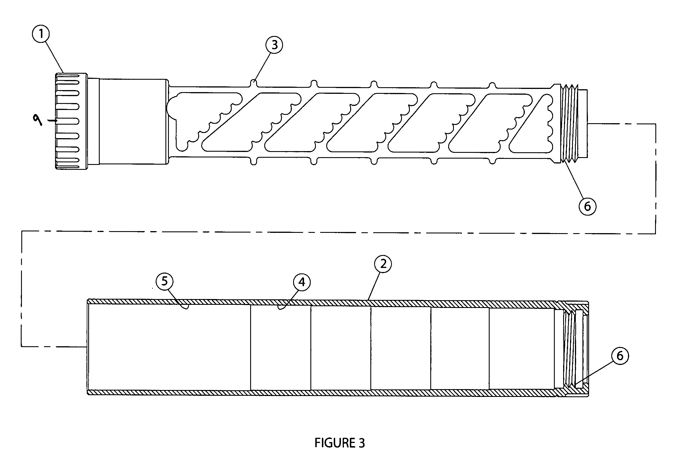
[0020]In FIG. 3, there is illustrated an example the noise suppressor tube 2 and the baffle core 8 separate from each other. Typically these two items are mach...


PUM


Abstract

An apparatus which provides for, noise suppressor tube with an internal tapered profile and baffle core which has an external tapered profile machined and designed to minimize friction between the two opposing surfaces which will better facilitate the disassembly of the noise suppressor unit after use.

Description

BACKGROUND OF THE INVENTION[0001]1. Field of Invention[0002]This invention generally relates to firearms, specifically to systems which facilitate the disassembly of a noise suppressor tube and its baffle core from each other. This system will allow the user to more effectively service and maintain the noise suppressor unit.[0003]2. Prior Art[0004]Previous systems exist for assembling and disassembling of a noise suppressor dating back to Hiram Maxim who invented the first noise suppressor. The majority of systems predating mine do not allow the end user to disassemble the noise suppressor for cleaning purposes. Eventually these sealed units become fouled with carbon, lead and copper which progressively reduce the effectiveness of the noise suppressor. Several designs such as the TAC65 utilize a very conventional disassembly method whereby the end cap of the noise suppressor is threadedly removed allowing for the removal of internal baffles. The failure of these designs is two folds...

Claims


Application Information

Patent Timeline
IPC IPC(8): F41A21/00
CPCF41A21/30
Inventor BRITTINGHAM, KEVIN TYSON
Owner JJE BRANDS LLC
Why Eureka
Try Eureka