System and method for preparing nanoparticles using non-thermal pulsed plasma

Inactive Publication Date: 2008-11-06
SAMSUNG ELECTRONICS CO LTD
View PDF4 Cites 8 Cited by
  • Summary
  • Abstract
  • Description
  • Claims
  • Application Information

AI Technical Summary

Benefits of technology

[0011]Example embodiments have been made in an effort to solve the problems of the prior art, and example embodiments provide a system and a method for preparing nanoparticles that prevent the formation of a thin film of nanoparticles to achieve improved uniformity of nanoparticles and high collection efficiency.

Problems solved by technology

Generally, the solid-to-particle conversion methods are not suitable for the preparation of particles having a size smaller than 3 micrometers.
However, the liquid-to-particle conversion methods have many limitations in preparing particles.
For example, the liquid-to-particle conversion methods cannot avoid the formation of chemical by-products.
Further, the liquid-to-particle conversion methods present difficulties in the application to applied products and the collection and migration of particles.
These limitations make the liquid-to-particle conversion methods unsuitable for practical application.
The chemical methods require a large quantity of energy with respect to the amount of particles to be prepared because the particles are prepared at high temperatures.
According to conventional methods and systems for preparing nanoparticles using plasma, a thin film is inevitably formed in a region where nanoparticles are to be collected, making it impossible to prepare nanoparticles having a uniform distribution in a stable manner.
Therefore, the conventional methods and systems have a problem in that the collection efficiency of nanoparticles is drastically lowered and a limitation in that nanoparticles cannot be additionally processed.

Method used


Image

  • System and method for preparing nanoparticles using non-thermal pulsed plasma
  • System and method for preparing nanoparticles using non-thermal pulsed plasma
  • System and method for preparing nanoparticles using non-thermal pulsed plasma

Examples


Embodiment Construction

[0022]Example embodiments will now be described in greater detail with reference to the accompanying drawings.

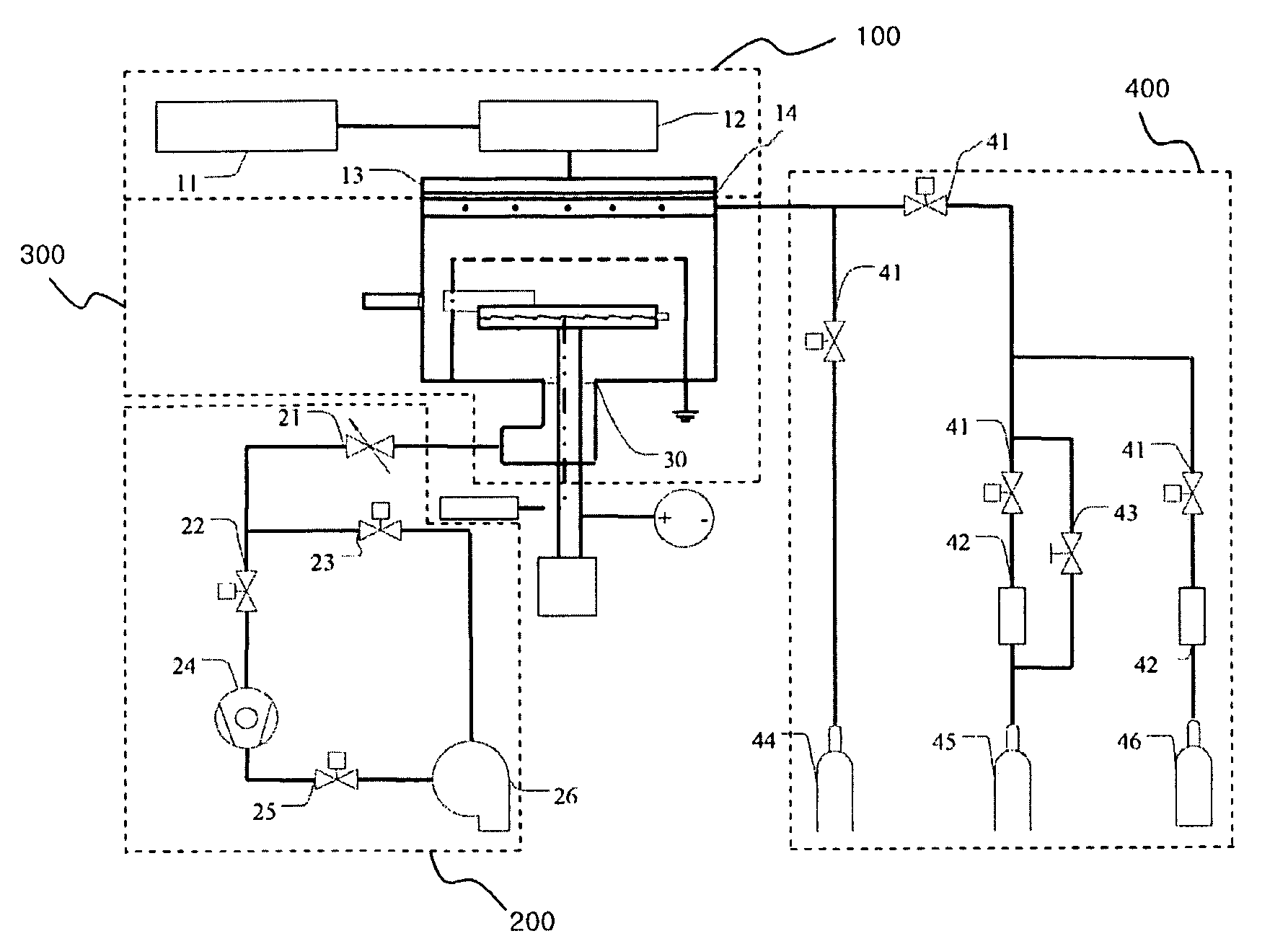
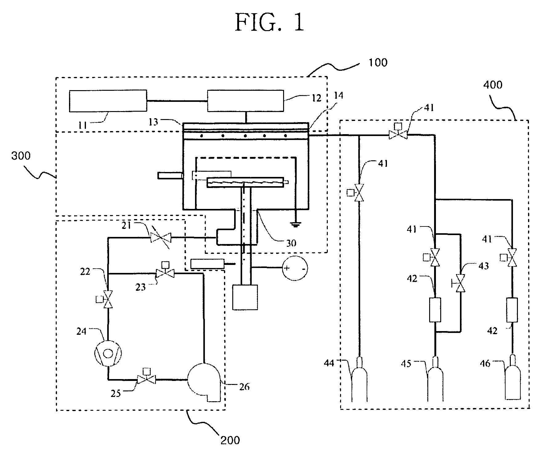
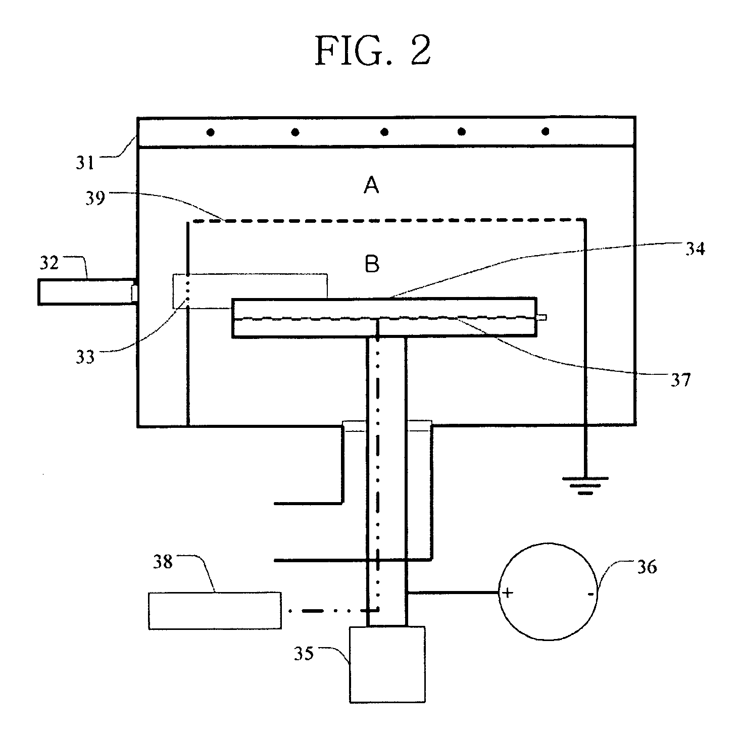
[0023]FIG. 1 is a schematic diagram illustrating a system for preparing nanoparticles according to example embodiments, and FIG. 2 is an enlarged schematic diagram illustrating a reaction chamber of the system of FIG. 1.

[0024]Example embodiments provide a system for preparing nanoparticles using non-thermal pulsed plasma. The system of example embodiments comprises: a reaction chamber including a gas inlet port, a receiver and an grounded separator and having a region where nanoparticles are to be formed and a region where the nanoparticles are to be received, the two regions being divided by the separator; a gas supply part for transferring a process gas and an ambient gas to the reaction chamber via the gas inlet port; a power supply part for producing plasma within the reaction chamber; and a flow control part for creating a vacuum and controlling the flow of the gases.

[0...


PUM


Abstract

A system for preparing nanoparticles using non-thermal pulsed plasma is provided. The system comprises a reaction chamber having two divided regions, i.e. a first region where nanoparticles are to be formed and a second region where the nanoparticles are to be received, to prevent the formation of a thin film of nanoparticles in the second region. The use of the system enables the preparation of nanoparticles with improved uniformity and high collection efficiency. In addition, collection and deposition of nanoparticles can be simultaneously performed in the second region. Therefore, the system can find applications in various fields, including devices, secondary cells and sensors. Further provided is a method for preparing nanoparticles using the system.

Description

PRIORITY STATEMENT[0001]This application claims priority under U.S.C. § 119 to Korean Patent Application No. 10-2007-0043542, filed on May 4, 2007, in the Korean Intellectual Property Office (KIPO), the entire contents of which are incorporated herein by reference.BACKGROUND OF THE INVENTION[0002]1. Field of the Invention[0003]Example embodiments relate to a system and a method for preparing nanoparticles using non-thermal pulsed plasma. More specifically, example embodiments relate to a system for preparing nanoparticles using non-thermal pulsed plasma which comprises a reaction chamber having two divided regions, i.e. a region where nanoparticles are to be formed and a region where the nanoparticles are to be received, and a method for preparing nanoparticles using the system.[0004]2. Description of the Related Art[0005]Nanoparticles are ultrafine particles whose size is in the nanometer range (10−9 m) corresponding to the size of several hundred atoms or molecules. Such nanometer...

Claims


Application Information

Patent Timeline
IPC IPC(8): H05H1/00
CPCH05H1/24H01J37/32146H01J37/32449H05H1/46H05H1/4652H05H2245/50B82B3/00B82Y40/00
Inventor NOH, CHANG HOKIM, TAE SUNGKIM, KWANG SU
Owner SAMSUNG ELECTRONICS CO LTD
Why Eureka
Try Eureka