
Agitation of electrolytic solution in electrodeposition

a technology of electrolysis solution and electrodeposition, which is applied in the direction of process and machine control, material dimension control, instruments, etc., can solve the problems of unwanted closed voids in vias and less uniform deplating rate, so as to reduce agitation power and improve compensation , the net plating rate is made more uniform

Inactive Publication Date: 2008-11-06
INVENSAS CORP
View PDF21 Cites 26 Cited by
  • Summary
  • Abstract
  • Description
  • Claims
  • Application Information

AI Technical Summary

Benefits of technology

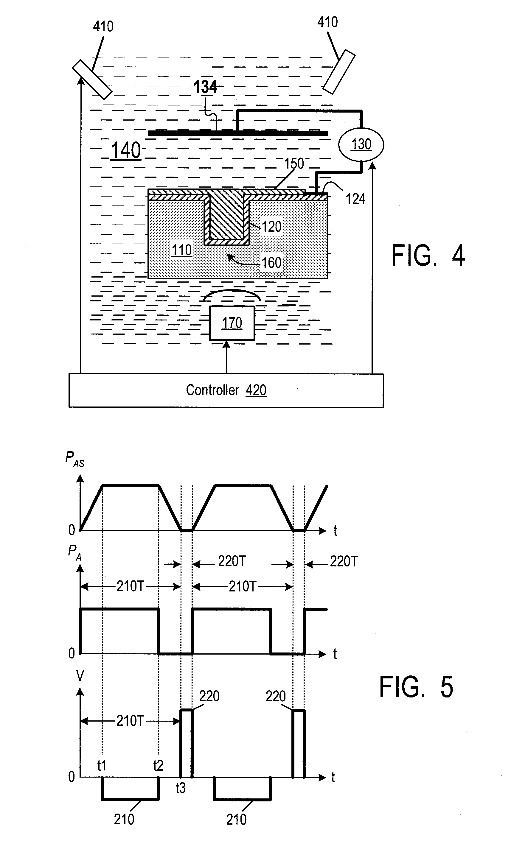
[0007]In some embodiments of the invention, the net plating rate is made more uniform by turning off agitation during the positive pulses or at least reducing the agitation power during the positive pulses. Turning off or reducing the agitation power during deplating makes the deplating rate less uniform, i.e. the ratio of the deplating rate at the top to the deplating rate at the via bottom increases. Hence, more metal can be deplated at the top per a given amount of metal deplated at the via bottom. The deplating non-uniformity provides better compensation for the plating non-uniformity during the negative pulses.

Problems solved by technology

An unwanted closed void may occur in the via as a result.
Turning off or reducing the agitation power during deplating makes the deplating rate less uniform, i.e. the ratio of the deplating rate at the top to the deplating rate at the via bottom increases.

Method used


Image

  • Agitation of electrolytic solution in electrodeposition
  • Agitation of electrolytic solution in electrodeposition
  • Agitation of electrolytic solution in electrodeposition

Examples


Embodiment Construction

[0015]The embodiments described in this section illustrate but do not limit the invention. The invention is defined by the appended claims.

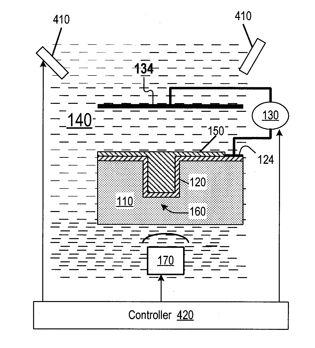
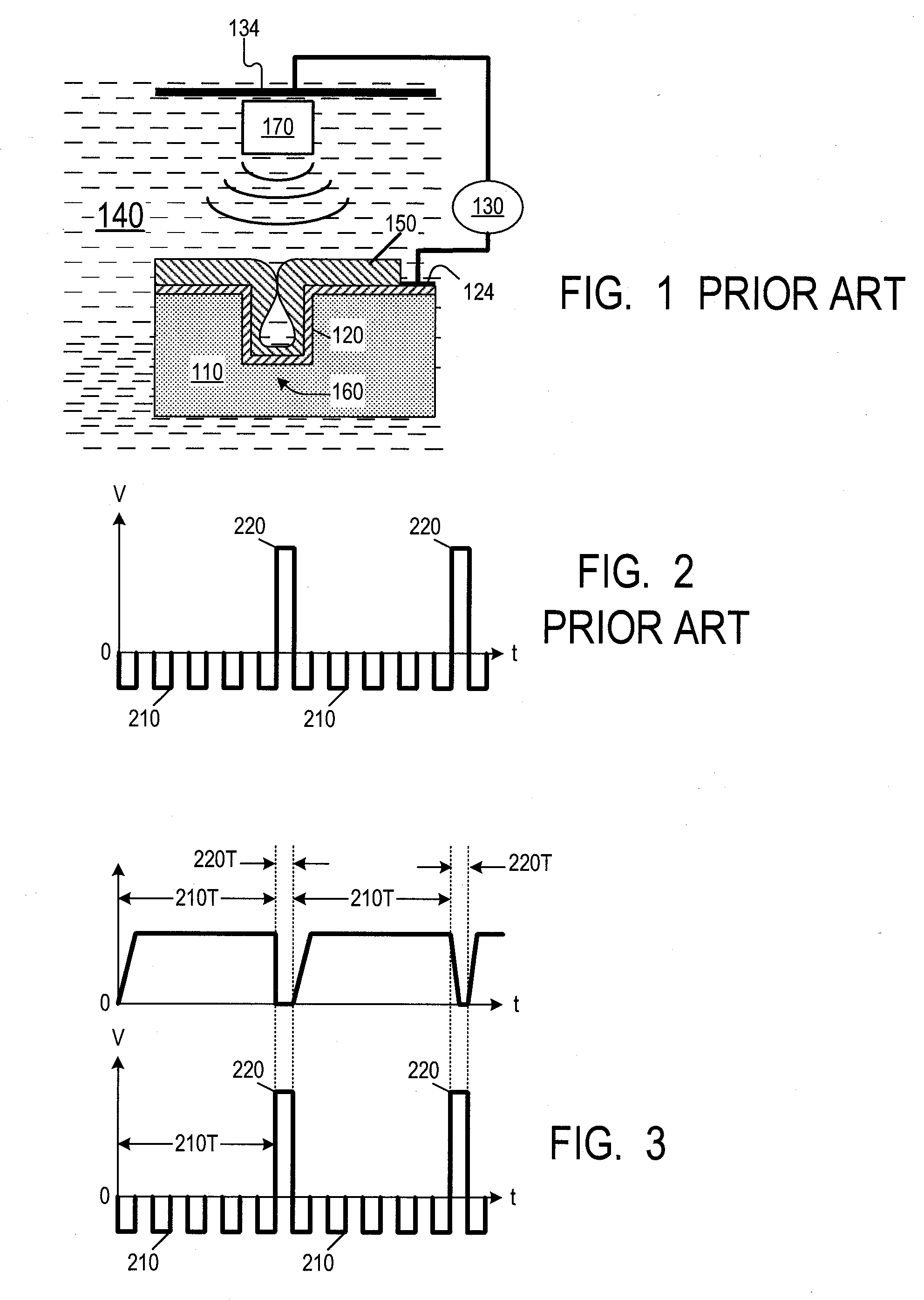
[0016]FIG. 3 illustrates timing diagrams for the electroplating voltage (the voltage at terminal 124 relative to terminal 134) and the agitation power in some embodiments of the present invention. The electroplating voltage is as in FIG. 2, with one or more negative pulses 210 delivered in each time period 210T, then one or more positive pulses 220 delivered in a time period 220T. The agitation power PA is positive during at least a portion of each time period 210T, but the agitation is turned off during each positive-pulse period 220T, or at least the maximum value of the agitation power in each period 220T is below the maximum value in each period 210T. Consequently, the deplating rate inside the via is lowered relative to the top of substrate 110.

[0017]The agitation can also be provided by mechanical stirring or perhaps in other ways. FIG. 4 i...


PUM

PropertyMeasurementUnit
Timeaaaaaaaaaa
Poweraaaaaaaaaa
Polarityaaaaaaaaaa

Abstract

In a reverse pulse plating of a substrate (110), the electrolytic solution is agitated with a greater power on forward pulses (210) than on reverse pulses (220). An ultrasound agitation source (170) can be positioned at the bottom of the substrate (110) if the anode (134) is at the top. The ultrasound source may contact the substrate's bottom. Other features are also provided.

Description

BACKGROUND OF THE INVENTION[0001]The present invention relates to agitation of electrolytic solution in electrodeposition.[0002]FIG. 1 illustrates electrodeposition (electroplating) of metal (e.g. copper) onto a substrate 110, e.g. a silicon wafer or a printed circuit board. Seed layer120 is formed on the substrate areas to be electroplated. Cathode terminal 124 of electric power supply 130 is connected to the seed layer, and anode terminal 134 is placed at a distance from substrate 110. The substrate and the terminals 124, 134 are immersed into an electroplating solution 140. As a result, metal layer 150 is deposited on seed layer 120 from metal ions supplied by salts in the electroplating solution and by anode terminal 134.[0003]If the metal is to be electroplated into a via 160 in the substrate surface, the electrodeposition rate near the via bottom can be lower than at the top, and the metal 150 may close the via at the top before a desired amount of metal 150 is deposited into ...

Claims


Application Information

Patent Timeline
IPC IPC(8): C25D21/10C25D17/00C25D21/12
CPCC25D5/08C25D5/18C25D5/20C25D21/10C25D21/12H01L21/2885H01L21/76877H01L21/76898H05K3/421H05K3/423H05K2201/09563H05K2203/0285H05K2203/0292H05K2203/1492
Inventor SAVASTIOUK, SERGEYKOSENKO, VALENTINBERGER, ALEXANDER J.
Owner INVENSAS CORP
Learn More