
Operational transconductance amplifier (OTA)

Active Publication Date: 2008-11-06
MICRON TECH INC
View PDF10 Cites 23 Cited by
  • Summary
  • Abstract
  • Description
  • Claims
  • Application Information

AI Technical Summary

Problems solved by technology

However, the application of the foregoing amplifier appears to be prone to relatively severe mismatches for the drain-to-source voltages of the mirror transistors.

Method used


Image

  • Operational transconductance amplifier (OTA)
  • Operational transconductance amplifier (OTA)
  • Operational transconductance amplifier (OTA)

Examples


Embodiment Construction

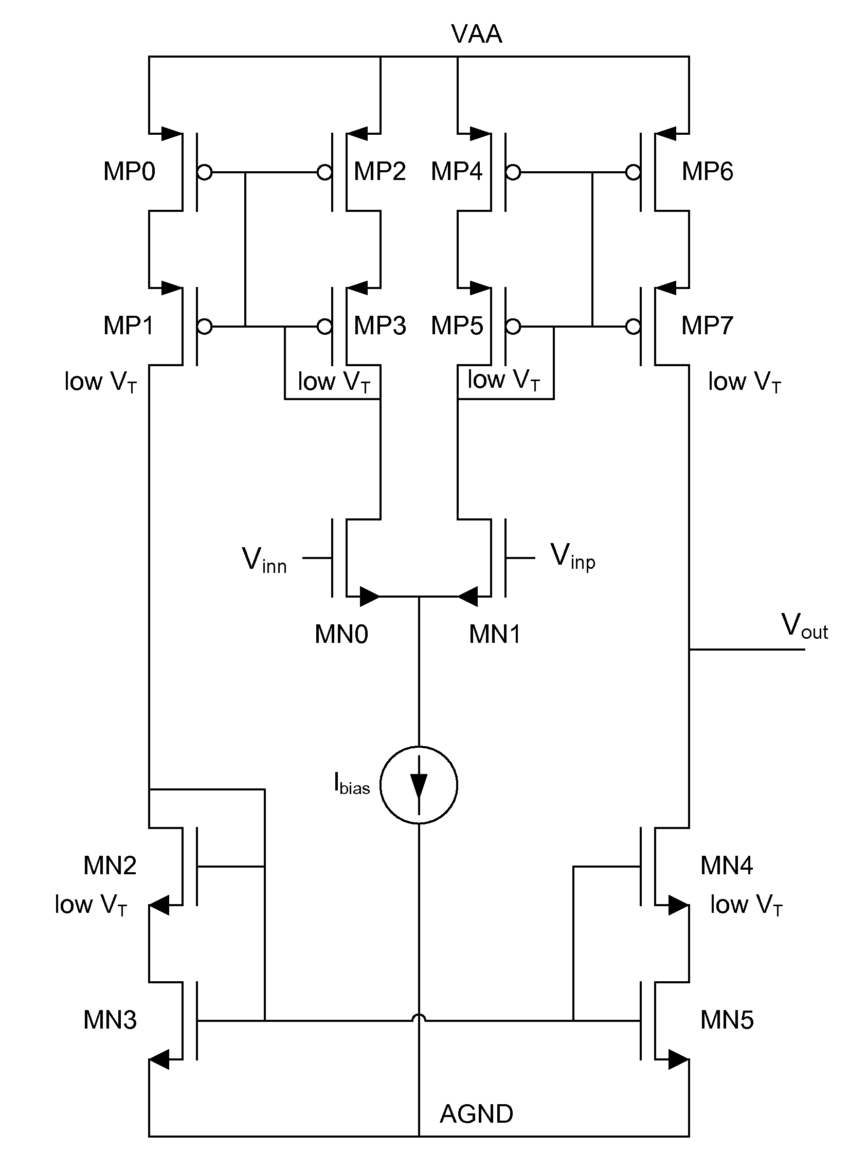
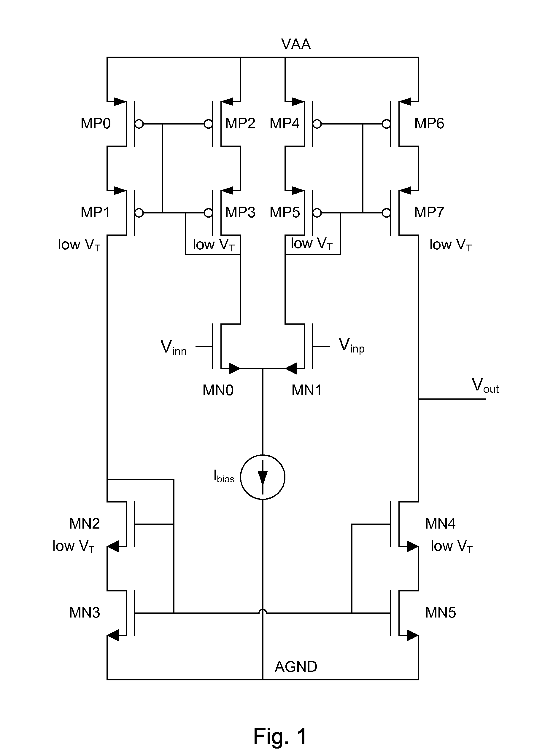
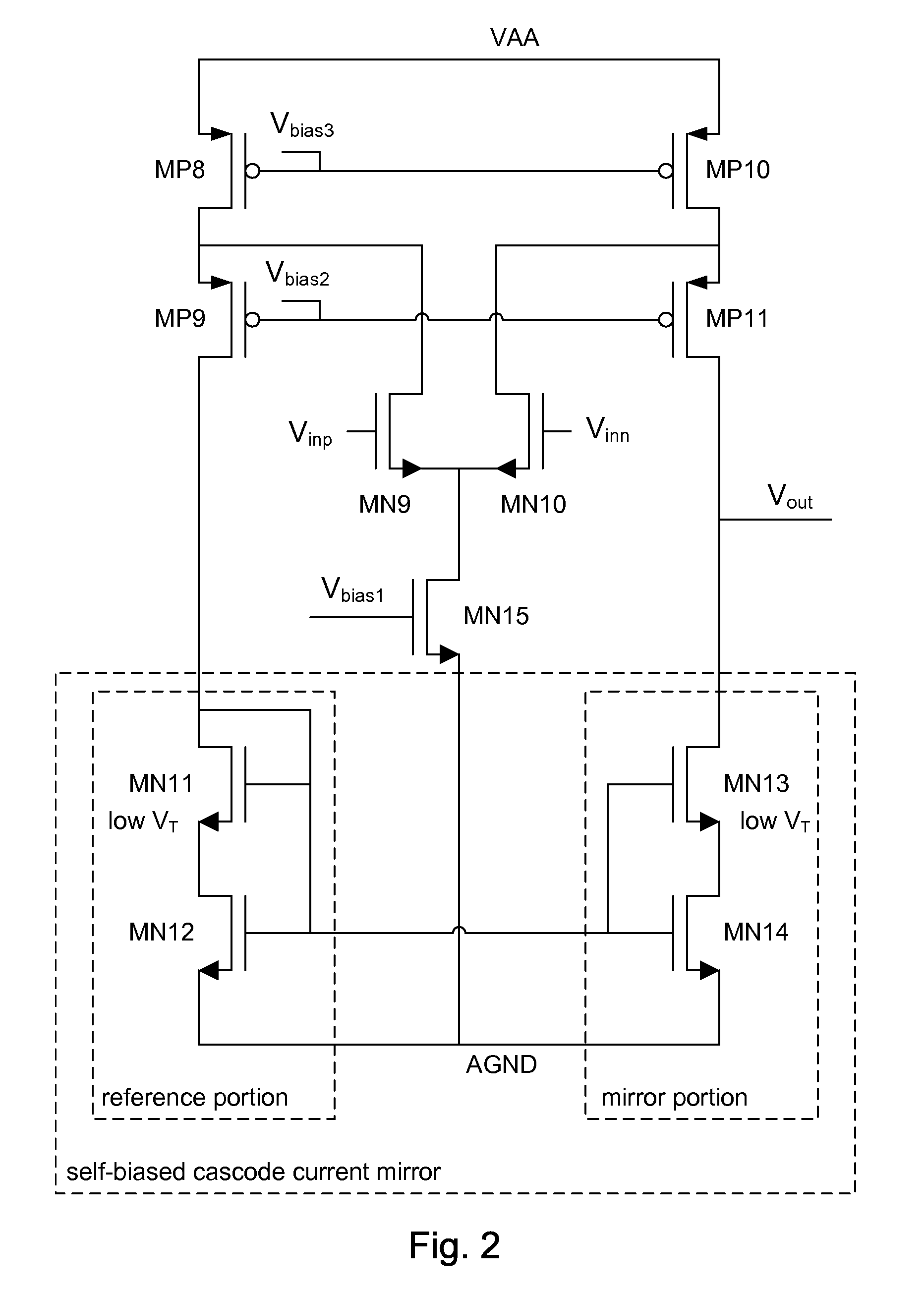
[0011]Circuit topologies are disclosed that provide an operational transconductance amplifier (OTA) with one or more self-biased cascode current mirrors. Applicable topologies include a current-mirror OTA and a folded-cascode OTA. An OTA is found in many analog circuits. Applications include, but are not limited to: buffers, attenuators, gain amplifiers, current amplifiers, filters, drivers, sensors, interface circuits between digital and analog domains, and the like.

[0012]One advantage of the self-biased cascode current mirror is that it saves extra bias voltages from having to be provided. This advantageously reduces power consumption, size, and cost. Although particular embodiments are described herein, other embodiments of the invention, including embodiments that do not provide all of the benefits and features set forth herein, will be apparent to those of ordinary skill in the art. For example, while the self-biased cascode current mirror is illustrated in the examples impleme...


PUM


Abstract

Apparatus and methods provide an operational transconductance amplifier (OTA) with one or more self-biased cascode current mirrors. Applicable topologies include a current-mirror OTA and a folded-cascode OTA. In one embodiment, the self-biasing cascode current mirror is an optional aspect of the folded-cascode OTA. The self-biasing can advantageous reduce the number of biasing circuits used, which can save chip area and cost. One embodiment includes an input differential pair of a current-mirror OTA.

Description

BACKGROUND[0001]1. Field of the Invention[0002]Embodiments of the invention generally relate to electronics. In particular, embodiments of the invention relate to analog integrated circuits.[0003]2. Description of the Related Art[0004]Analog amplifiers are widely use in electronic devices. Applications include, but are not limited to: buffers, attenuators, gain amplifiers, current amplifiers, filters, drivers, interface circuits between digital and analog domains, and the like. One type of amplifier is known as an operational transconductance amplifier (OTA). An OTA receives a differential input voltage and generates an output current. OTAs are commonly used in, for example, variable frequency oscillators, filters, variable gain amplifiers, and the like.[0005]It is desirable for an analog amplifier to have relatively good performance, to be inexpensive to manufacture, to be usable in a wide range of power supply voltages, to be able to swing relatively large output voltages, and the...

Claims


Application Information

Patent Timeline
IPC IPC(8): H03F3/45
CPCH03F3/3022H03F3/45192H03F2200/453H03F2203/30015H03F2203/45028H03F2203/45292H03F2203/45626
Inventor WILLASSEN, TRYGVEMARTINUSSEN, TORE
Owner MICRON TECH INC
Learn More