
Tunable Dielectric Resonator Circuit

a dielectric resonator and circuit technology, applied in the direction of resonators, basic electric elements, waveguide devices, etc., can solve the problems of high sensitive dielectric resonator circuits, inability to achieve tunability over a 200 mhz frequency range and bandwidth range from 5 mhz to 30 mhz for a single basic circuit design, and the tuning screw cannot permit significant changes in coupling strength between the dielectric resonators

Inactive Publication Date: 2008-11-06
COBHAM DEFENSE ELECTRONICS SYST CORP
View PDF42 Cites 140 Cited by
  • Summary
  • Abstract
  • Description
  • Claims
  • Application Information

AI Technical Summary

Benefits of technology

[0020]In accordance with a second aspect of the invention, a dielectric resonator circuit is provided comprising an enclosure, an input coupler, an output coupler and at least one dielectric resonator disposed in the enclosure, each resonator comprising a first body component comprising first and second substantially parallel faces, the first and second faces joined by at least one third face running between the first and second faces defining a periphery of the body, a first through opening in the body extending in a first direction perpendicular to the first and second faces, the first opening defining a fourth, inner face of the body, and a second opening in a second direction perpendicular to the first direction extending from the at least one third face to the fourth face, and a second body component comprising a plug shaped and positioned to fit at least partially within the second opening, the second body component adjustably mounted to the enclosure so as to be movable relative to the first body component in the second direction to permit tuning of the circuit.

Problems solved by technology

However, such tuning screws do not permit significant changes in coupling strength between the dielectric resonators.
Thus, for a standard dielectric resonator filter, tunability over a 200 MHz frequency range and over a bandwidth range from 5 MHz to 30 MHz for a single basic circuit design is not reasonably possible.
Furthermore, the Q of dielectric resonator circuits is highly sensitive to tuning, particularly at very high frequencies such as that required for WiMAX.

Method used


Image

  • Tunable Dielectric Resonator Circuit
  • Tunable Dielectric Resonator Circuit
  • Tunable Dielectric Resonator Circuit

Examples


Embodiment Construction

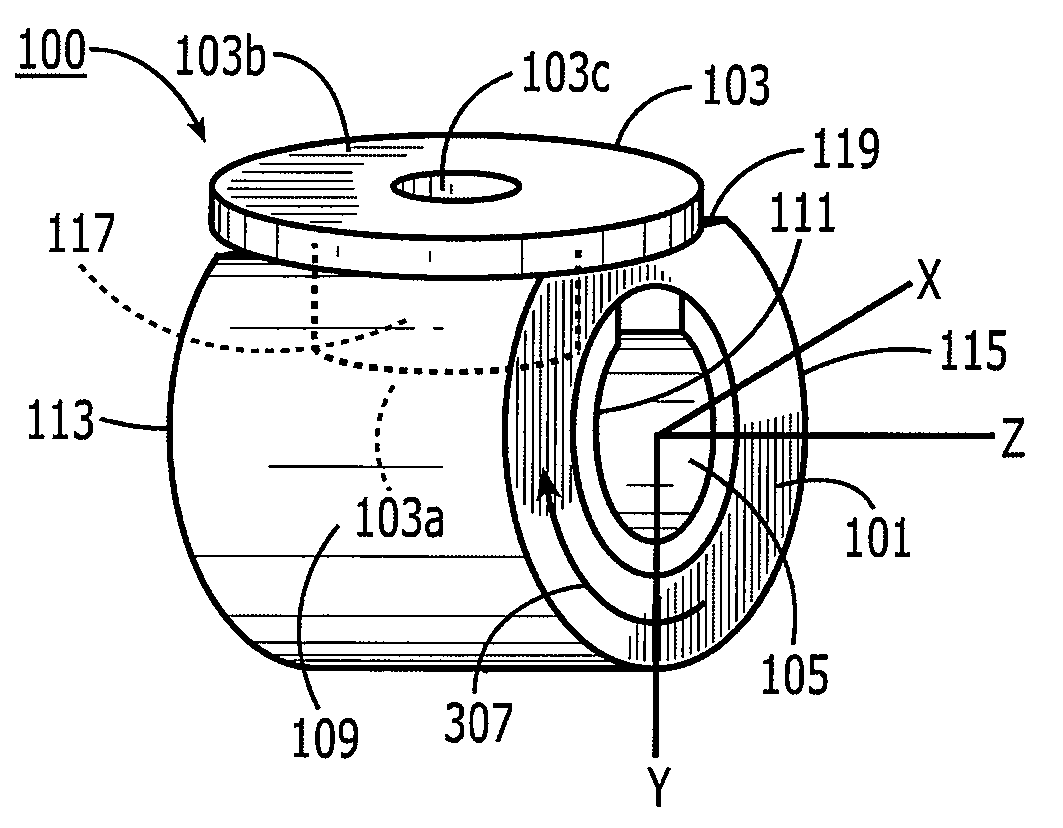
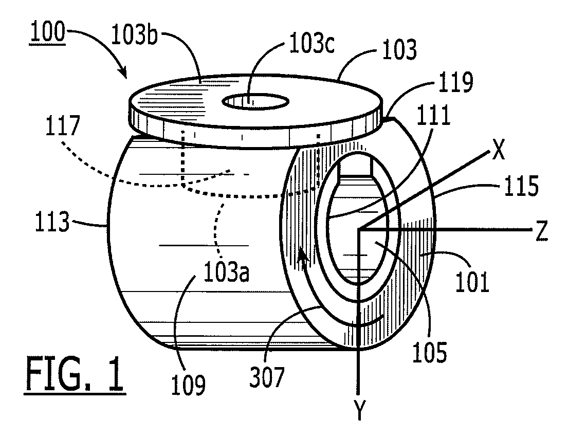
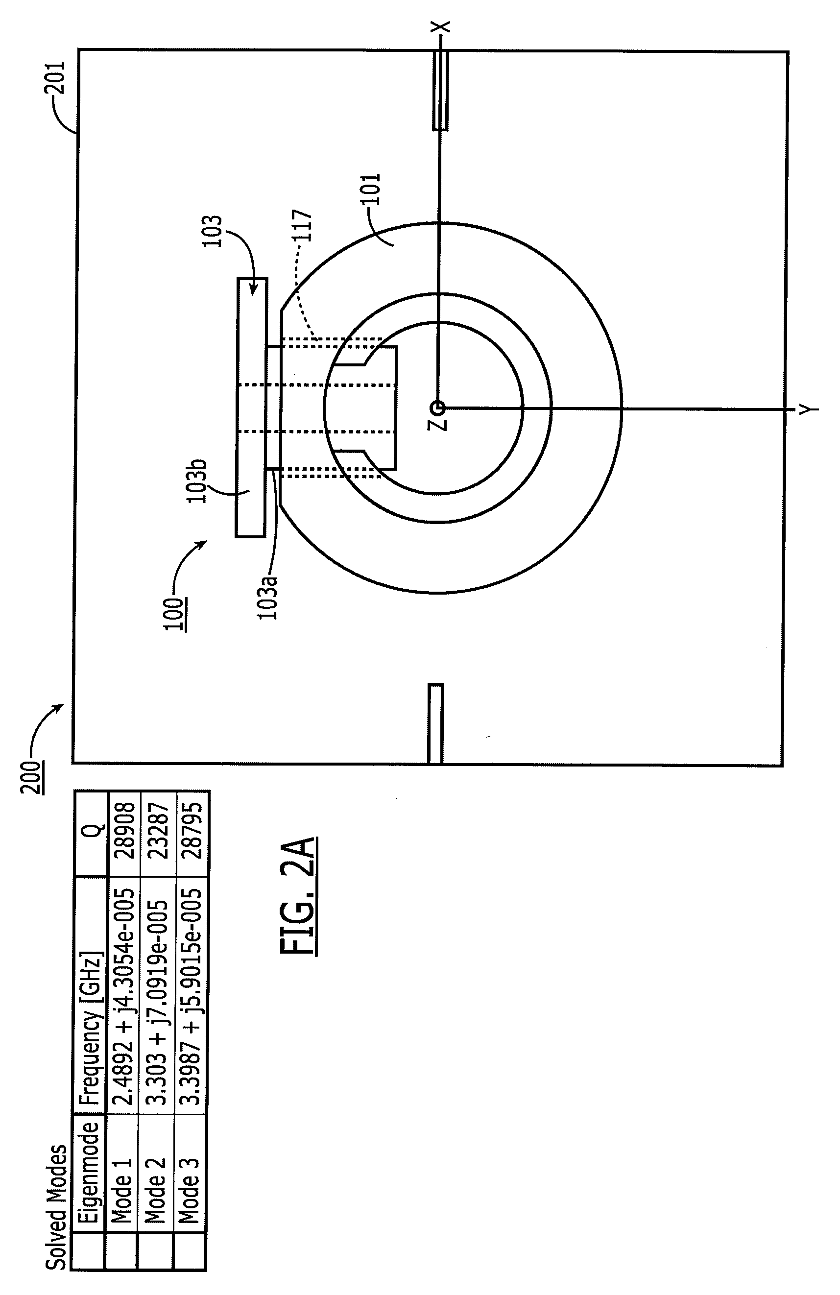
[0036]FIG. 1 is a perspective view illustrating a dielectric resonator 100 that is highly tunable, particularly in resonance (or center) frequency. The resonator comprises two body components 101 and 103. The first, main body component 101 is generally annular in shape with a through hole 105 in the longitudinal (z) dimension. The longitudinal dimension (z axis) is the direction perpendicular to the transverse electric (TE) mode direction (see arrow 307) and generally parallel to the lines of the magnetic field in the resonator at the geometric center of the resonator (i.e., on the z axis in the Figures). The first body component 101 of this resonator is somewhat similar in shape to a conventional cylindrical dielectric resonator with a longitudinal through hole. It has an outer annular surface 109, an inner annular surface at 111 and sidewalls 113, 115 connecting the outer and inner annular surfaces 109, 111. However, in addition, there is a second through hole 117 extending betwee...


PUM


Abstract

A dielectric resonator circuit is provided that is tunable over a broad frequency range and / or a broad bandwidth range. The center frequency is made tunable over a broad range by use of a dielectric tuning plug that is positioned in a through hole within the resonator. The bandwidth is made tunable over a broad range by tilting the resonators relative to the enclosure to increase the effective height of the cavity as seen by the resonator.

Description

BACKGROUND[0001]1. Field of the Invention[0002]The invention pertains to dielectric resonator circuits. More particularly, the invention pertains to dielectric resonator filters that are tunable over a broad bandwidth range and a broad frequency range.[0003]2. Background of the Invention[0004]WiMAX (Worldwide Inter-Operability For Microwave Access) is a wireless industry coalition organized to advance IEEE 802.16 standards for broadband wireless access networks. WiMAX 802.16 technology is adapted to enable multimedia applications with a wireless connection. WiMAX 802.16 has a range of up to 30 miles, presenting network providers with a wireless, last-mile solution for wideband data transmission.[0005]According to the WiMAX IEEE 802.16 specification, WiMAX transmitters transmit data at frequencies between 2500 MHz and 2700 MHz or between 3500 MHz and 3700 MHz and may have channel bandwidths between 5 MHz and 30 MHz.[0006]Accordingly, there is a need to supply the WiMAX 802.16 industr...

Claims


Application Information

Patent Timeline
IPC IPC(8): H01P7/10H01P1/20
CPCH01P1/2084H01P7/10
Inventor PANCE, KRISTI DHIMITER
Owner COBHAM DEFENSE ELECTRONICS SYST CORP
Learn More