
Apparatus and method for producing concrete

Inactive Publication Date: 2008-11-06
JONEL ENG
View PDF12 Cites 35 Cited by
  • Summary
  • Abstract
  • Description
  • Claims
  • Application Information

AI Technical Summary

Benefits of technology

[0005]While the mixture is going through its final mixing stages, the next batch of pre-measured materials enter the mixer to be blended. The blending time is equal to or less than the time it takes to process the initial mixture through the horizontal screw conveyor, thereby, reducing any time span between batches.
[0006]Raw materials are weighed in their respective vessels and then discharged to intermediary “holding” hoppers. The materials stay held in their hoppers until the mixer is ready to receive them. Once the weighing vessels are purged, they become ready for the next weigh cycle. Therefore, the process remains continuous from batch to batch and allows for different mix proportions and batch sizes.
[0007]Cement reduction is provided by means of premixing the cement, sand, and water separately from the course aggregates, in the twin-shaft mixer. This allows the cement to become more hydrated and offer better adhesion when coming into contact with the course aggregates. Embodiments of this invention produce high-strength ready-mixed concrete, and are capable of reducing the relative quantity of cement per batch. Another aspect of these embodiments is to decrease the overall mixing time for each batch. Another aspect is to provide continuous output of concrete.
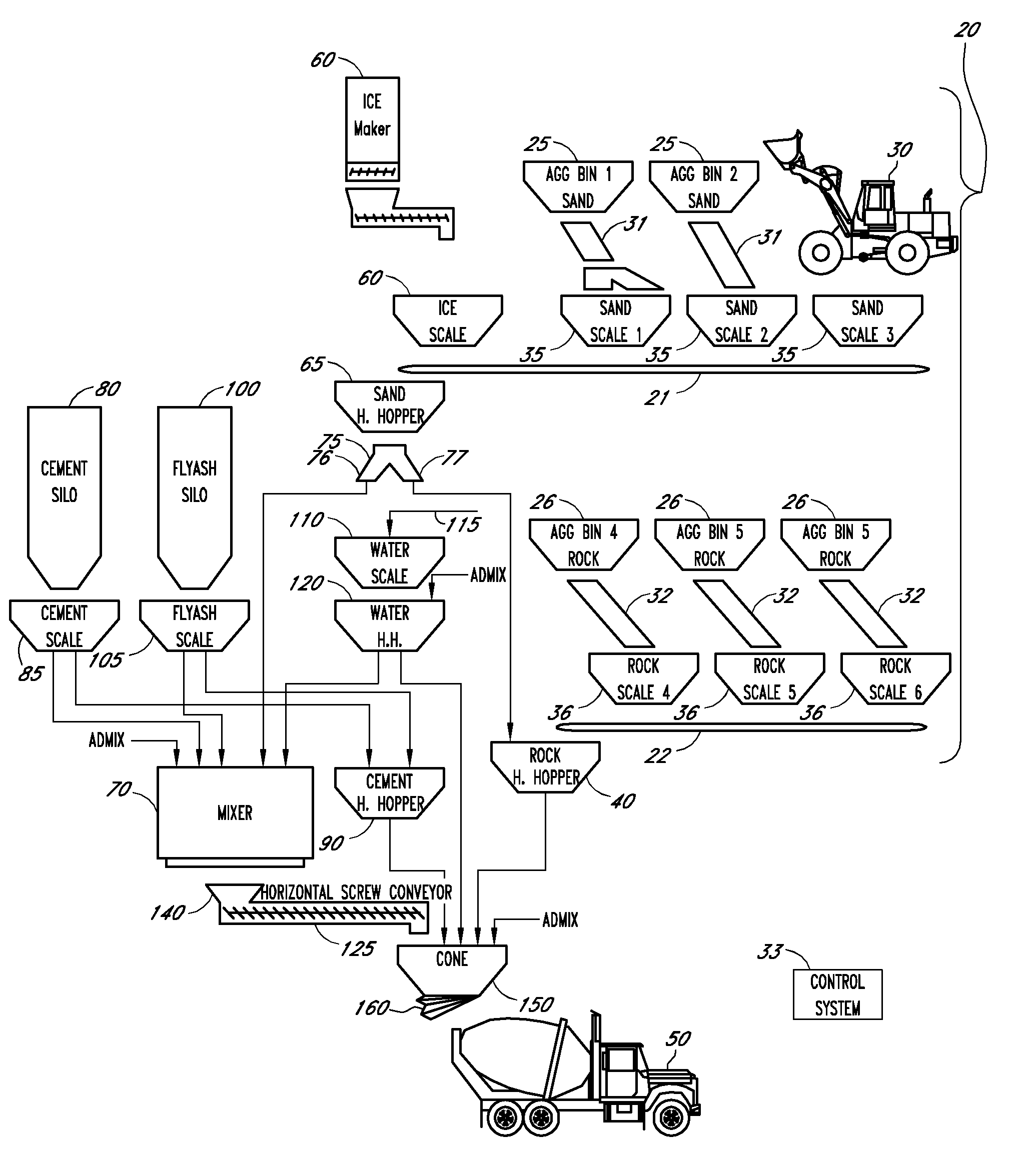
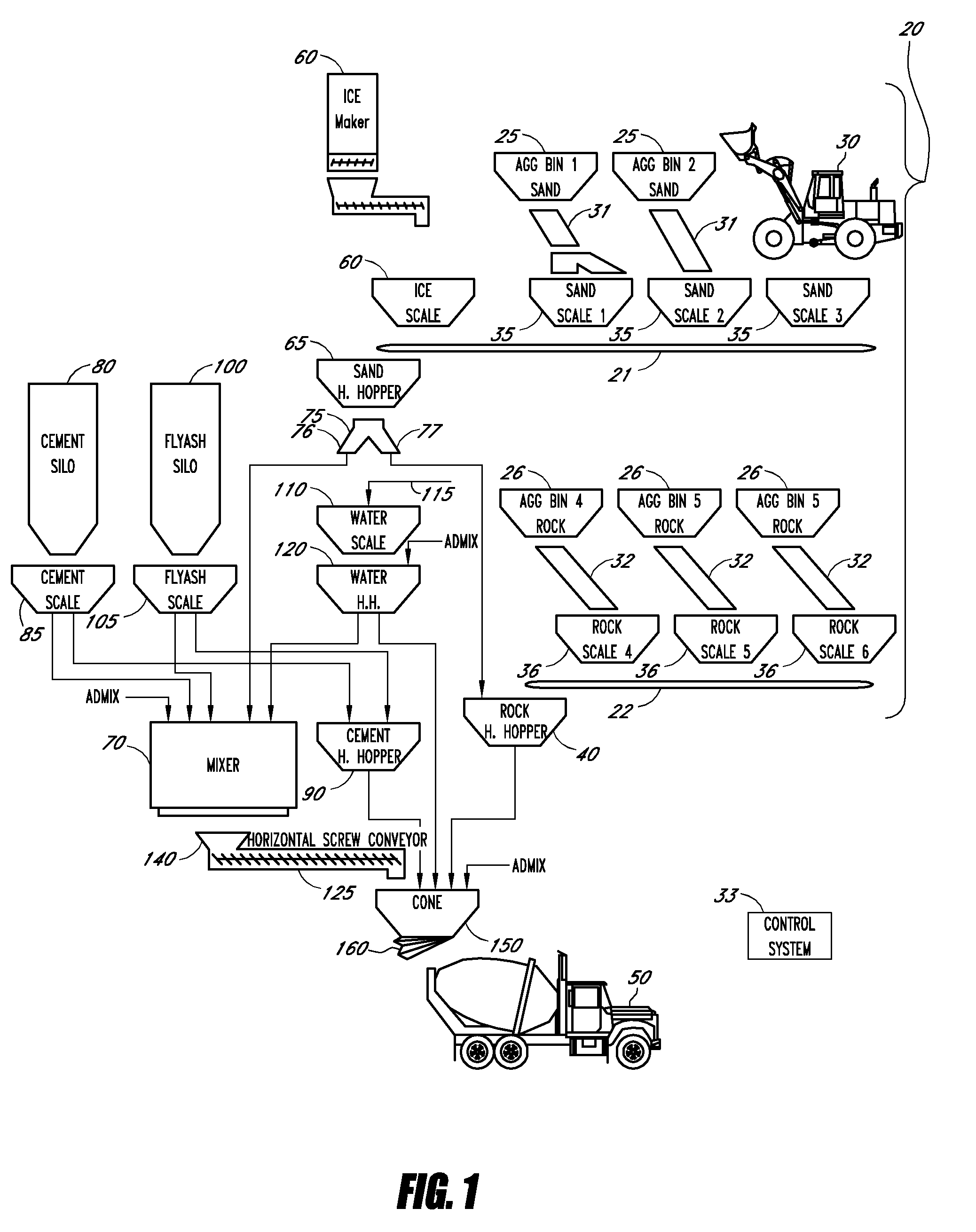
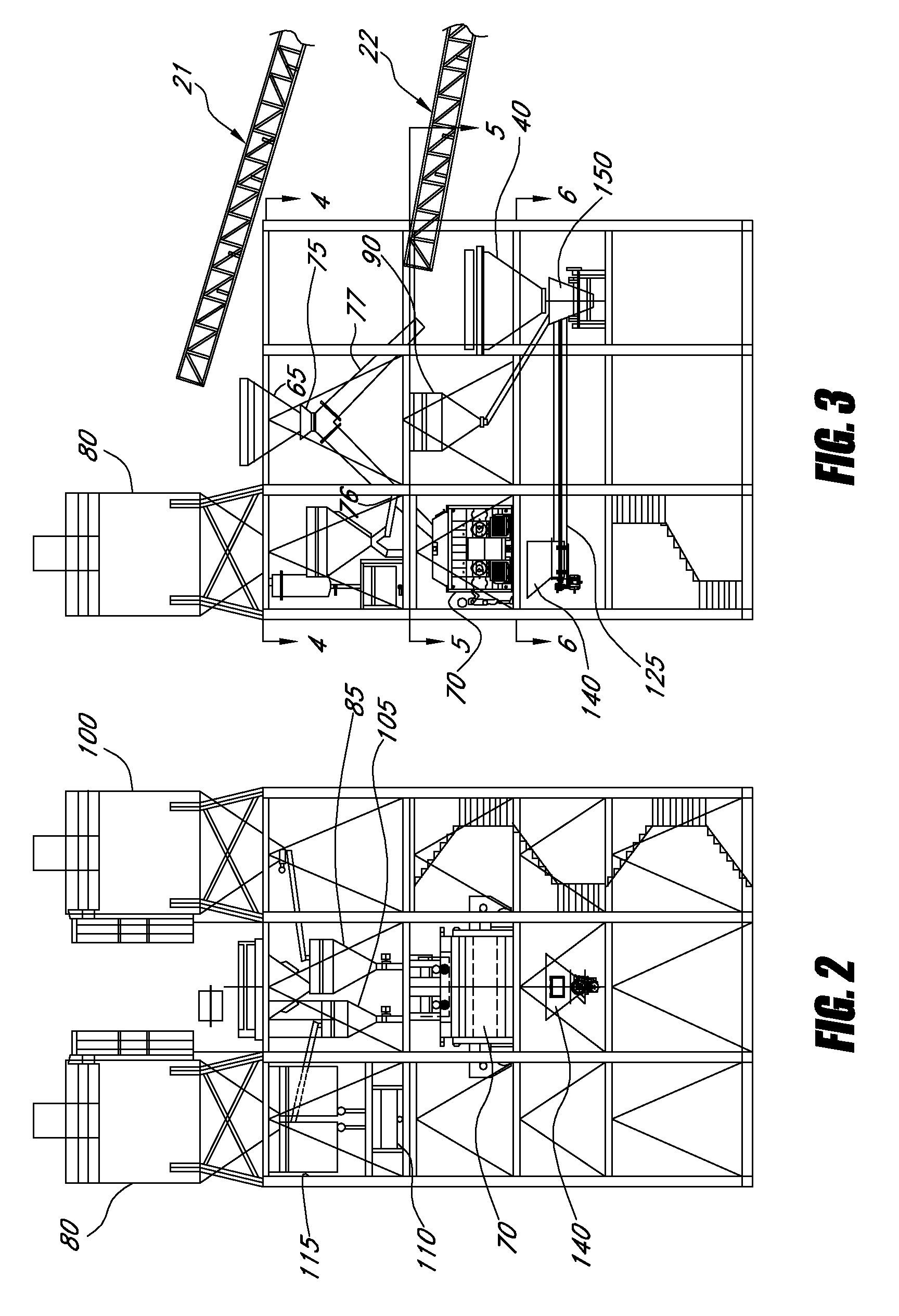
[0008]In one aspect of the invention, an apparatus for producing substantially continuous batches of high-strength concrete is provided, said apparatus utilizing a multi-stage mixing process so the concrete is ready to be pumped into a truck immediately after a preceding concrete truck has been loaded with concrete. The apparatus includes sand and rock scales adapted to reverse-weigh a predetermined quantity of sand and rock, and discharge said sand and rock onto respective sand and rock conveyors. The apparatus can also include sand and rock hoppers to receive and hold sand and rock from the respective conveyors. The apparatus can further include scales for cement, flyash, and water, that are adapted to receive and hold these materials from cement and flyash silos and a water supply until a predetermined weight of each ingredient is reached. A control system responsively connects to the scales and hoppers, and is adapted to cause the sand hopper, cement scale, flyash scale, and water scale to release their contents into a mixer and to subsequently refill for a subsequent batch. Adapted to receive mixed ingredients from the mixer can be a horizontal screw conveyor, which further mixes said ingredients to form a mixture, and to expel said mixture at an elevated pressure to a transition cone. The transition cone is positioned to receive the mixture from the horizontal screw conveyor and the rock from the rock hopper and convey said mixture and rock to a mixer truck at high speed. The apparatus can enable successive loading and mixing of measured quantities of cement, flyash, sand, rock, and water while the conveyor is delivering a mixed batch to the mixer truck so that successive batches of concrete are conveyed by the conveyor in time to be loaded into successive mixer trucks without any appreciable delay between the loading of each successive mixer truck.

Problems solved by technology

The process can take an extensive period of time, causing delays in delivery.
Attempts to accelerate the process can potentially reduce the quality of the concrete.

Method used


Image

  • Apparatus and method for producing concrete
  • Apparatus and method for producing concrete
  • Apparatus and method for producing concrete

Examples


Embodiment Construction

[0028]The disclosure herein provides systems and methods for high-strength concrete. The disclosure herein additionally provides systems and methods for continuous production of batches of concrete. A computer control system can be used to coordinate the various elements of a concrete batch plant and accelerate production. Further, elements can be provided to the batch plant to cause the concrete to discharge to a mixer truck at high pressure and speed, accelerating the delivery and transport of the concrete.

[0029]The concrete produced by the systems and methods disclosed herein can have a strength up to approximately 20 percent greater than concrete formed with prior art concrete technologies using the same ingredient proportions. Thus, the present invention can potentially provide stronger concrete at a faster rate.

Plant Form & Function

[0030]A computer control system 33 is connected to each of the plurality of components of the batch plant. The computer control system 33 can compr...


PUM

PropertyMeasurementUnit
Fractionaaaaaaaaaa
Timeaaaaaaaaaa
Timeaaaaaaaaaa

Abstract

Apparatus and methods produce substantially continuous batches of high-strength concrete. Portland cement, flyash, sand, water, and concrete chemical additives are premixed in a multi-stage process, prior to final mixing with the coarse aggregates. In sequence, the complete mixing process includes: 1) a twin-shaft compulsory mixer to blend the materials, then disposing the mixture into; 2) a horizontal screw conveyor, continuously mixing as the mixture passes through the housing, thereby disposed simultaneously with the coarse aggregates into; and 3) the mixer concrete delivery truck, wherein the concrete is mixed further.

Description

CROSS-REFERENCE TO RELATED APPLICATIONS[0001]This application claims priority from U.S. Provisional No. 60 / 915,598, filed May 2, 2007, the entire contents of which are incorporated herein by reference.FIELD OF THE INVENTION[0002]This invention relates generally to an apparatus and methods for producing ready-mixed concrete and more particularly to an apparatus and methods for continuous production of ready-mixed concrete.DESCRIPTION OF THE RELATED ART[0003]In the production of concrete, a variety of materials must be measured and mixed. The process can take an extensive period of time, causing delays in delivery. Attempts to accelerate the process can potentially reduce the quality of the concrete. Therefore, fast and high quality methods and apparatuses for producing concrete are needed.SUMMARY OF THE INVENTION[0004]In one embodiment, apparatuses and methods produce substantially continuous batches of high-strength concrete. Accordingly, concrete is ready to be pumped into a concre...

Claims


Application Information

Patent Timeline
IPC IPC(8): B28C5/38
CPCB28C5/468B28C7/0418B28C7/0436B28C7/0481B28C9/002
Inventor THORNTON, RICHARDLAWSON, CRAIGCRAIN, CHRIS
Owner JONEL ENG
Learn More