
Intersection timing scheme estimation method based on electronic police checkpoint data

A technology for intersections and electric police cards, which is applied in traffic control systems, traffic control systems, instruments, etc. of road vehicles, and can solve problems such as the inability to obtain signal timing schemes, the deviation of timing schemes, and the lack of full parameters of timing schemes, etc.

Active Publication Date: 2021-01-08
TONGJI UNIV
View PDF8 Cites 3 Cited by
  • Summary
  • Abstract
  • Description
  • Claims
  • Application Information

AI Technical Summary

Problems solved by technology

However, in practice, due to the detection system clock offset or human intervention, the accurate signal timing scheme is often not available, or there is a large deviation between the timing scheme provided by the traffic control department and the actual running timing scheme
[0003] Most of the existing timing estimation methods are based on floating vehicles or sampled trajectory data through deterministic traffic wave analysis methods and non-deterministic probability statistics methods. For timing estimation methods based on vehicle trajectory data, the calibration of stop lines and The space-time coordinates of vehicles joining and leaving the queue are the primary link, so the capture rate and upload frequency of vehicle trajectories have a great impact on the estimation accuracy. In terms of estimated parameters, the cycle length and the green light duration of a single flow direction are the most common estimates parameters, but the research on the estimation of the full parameters of the timing scheme is still rare, and the estimation of the phase structure is mostly based on the selection of predetermined candidate phase structure schemes

Method used


Image

  • Intersection timing scheme estimation method based on electronic police checkpoint data
  • Intersection timing scheme estimation method based on electronic police checkpoint data
  • Intersection timing scheme estimation method based on electronic police checkpoint data

Examples


Embodiment

[0085] Such as Figure 4 As shown, the present invention provides a method for estimating the timing scheme of an intersection based on bayonet electric police data, comprising the following steps:

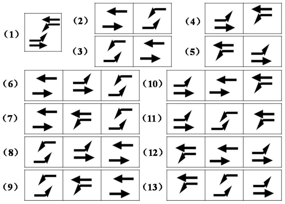
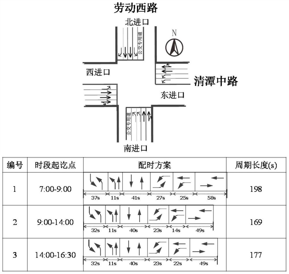
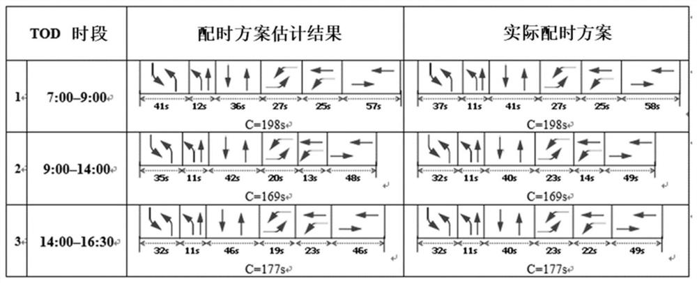
[0086] 1) Acquire the passing data of the electric police bayonet detectors in the lanes where all the controlled flow directions are located at the intersection, preprocess to obtain the headway sequence of all the controlled flow directions and the arrival feature vector of the vehicle, and perform k -means clustering to obtain a rough estimate of the cycle length and the corresponding initial cycle passing point set, and define the constraints of the cycle length and phase difference estimation;

[0087] 2) For all possible phase combinations of the controlled flow direction, by defining dummy variables that characterize the relationship between the turn-on sequence of the green light time and the length of the green light in the straight flow direction and the left-turn flow d...


PUM


Abstract

The invention relates to an intersection timing scheme estimation method based on electronic police checkpoint data. The method comprises the following steps: 1) constructing a double-layer planning problem model for intersection timing scheme estimation; 2) acquiring constraint conditions of period length, phase difference and green signal ratio estimation; 3) for all possible phase combinationsof the controlled flow direction, defining a dumb variable representing the relationship between the turn-on sequence of the green light time of the straight flow direction and the left-turn flow direction and the length of the green light, and obtaining a constraint condition of a phase structure; and 4) solving a double-layer planning problem of intersection timing scheme estimation by adoptinga least square method in combination with constraint conditions of period length, phase difference, phase structure and green signal ratio estimation to obtain a final estimated timing scheme. Compared with the prior art, the method has the advantages of full-parameter estimation, high estimation precision, wide applicability and the like.

Description

technical field [0001] The invention relates to the technical field of traffic operation signal timing, in particular to a method for estimating an intersection timing scheme based on electric police bayonet data. Background technique [0002] As a sign of discontinuous flow, the signal timing scheme makes the traffic flow have periodic characteristics in the time dimension. It is an important input in estimating traffic operation evaluation indicators such as queue length and delay, and it is also an optimization problem when optimizing signal control. Decision variables, although the current signal control field has developed to the stage of induction control and adaptive control (such as SCOOT, SCATS, etc.), the multi-period timing control mode still occupies a dominant position in most countries and regions. However, in practice, due to the clock offset of the detection system or human intervention, the accurate signal timing scheme is often not available, or there is a ...

Claims


Application Information

Patent Timeline
IPC IPC(8): G08G1/082G08G1/083
CPCG08G1/082G08G1/083
Inventor 唐克双姚佳蓉吴浩
Owner TONGJI UNIV
Learn More