Scheduling in a Wireless Multi-Hop Relay Network

a wireless multi-hop relay and wireless technology, applied in power management, signalling characterisation, channel coding adaptation, etc., can solve the problems of increasing the cost of building and maintaining the system, requiring fast protocols, and imposing additional overhead, so as to increase the average data rate, reduce variance, and improve the effect of data ra

Active Publication Date: 2008-11-06
TELEFON AB LM ERICSSON (PUBL)
View PDF9 Cites 133 Cited by
  • Summary
  • Abstract
  • Description
  • Claims
  • Application Information

AI Technical Summary

Benefits of technology

[0011]It is also an object to provide improved scheduling in wireless networks such as wireless relaying networks.
[0026]For the case when the originating transmitting node and at least one of the receiving nodes are equipped with multiple antennas and a MIMO / MISO-based opportunistic communication scheme is used, at least part of the relaying nodes may be equipped with one or multiple antennas, and one of the receiving nodes may be selected for MIMO / MISO based communication to create a richer channel, i.e. a channel that will increase the overall end-to-end (ETE) channel capacity even further. In particular, spatial multiplexing based MIMO may be used to offer high spectral efficiency. The feedback for this scheme is preferably a vector of channel qualities describing the quality of each MIMO sub-channel.

Problems solved by technology

In addition, the cost aspect of building and maintaining the system is expected to become even more important in the future.
Cooperative relaying schemes that perform well usually rely on precise channel state information, but then require fast protocols and impose additional overhead.

Method used


Image

  • Scheduling in a Wireless Multi-Hop Relay Network
  • Scheduling in a Wireless Multi-Hop Relay Network
  • Scheduling in a Wireless Multi-Hop Relay Network

Examples


performance example

[0073]In the following example, it is assumed that V=6 relays (RS1-RS6) are placed in a hexagon around an originating transmitter such as a base station (BS), and that U receivers such as mobile stations (MS1-MSU) are positioned a distance away from the transmitter that is roughly twice the transmitter-relay distance. The basic configuration is shown in FIG. 5.

[0074]First, amplify and forwarding will be assumed. Starting from the signal to noise ratio in a receiver as presented in [6], this relation is modified for opportunistic cooperative relaying by incorporating a random phase factor exp(iφv,u) for each relay (RS) v and each receiver (MS) u. The effective SNR for a receiver (mobile station) u is then expressed as:

ΓEff,u=∑n=1Nb_v(AF)ΓRS,v·ΓMS,u,vΓRS,v+ΓMSu,k+1·jϕu,v2∑n=1Nb_v(AF)2(3a)

[0075]Note that the arguments in the square root of (3a) are instantaneous values, reflecting current and instantaneous channel conditions, in contrast to the average values used for bv.

[0076]In the d...


PUM


Abstract

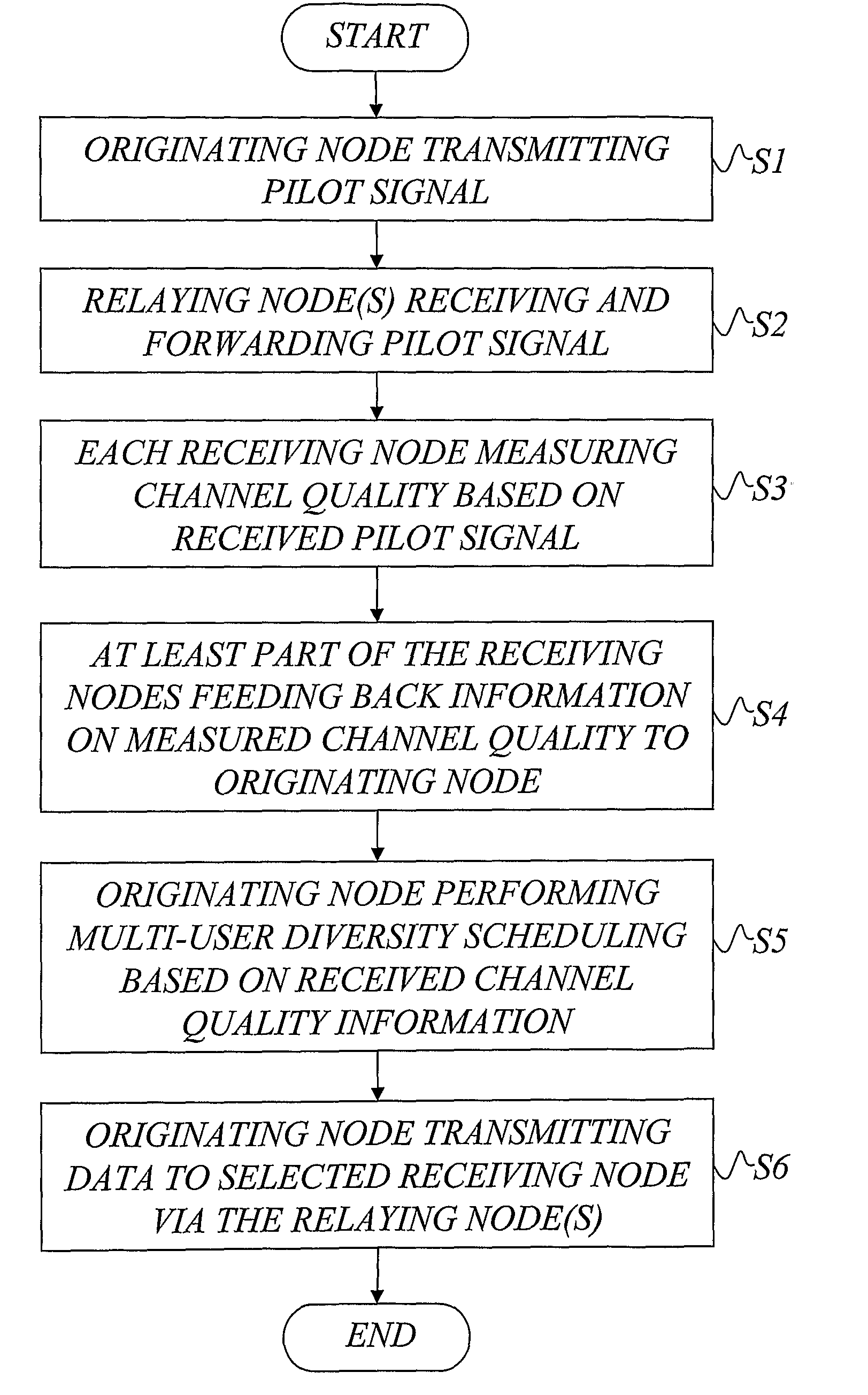
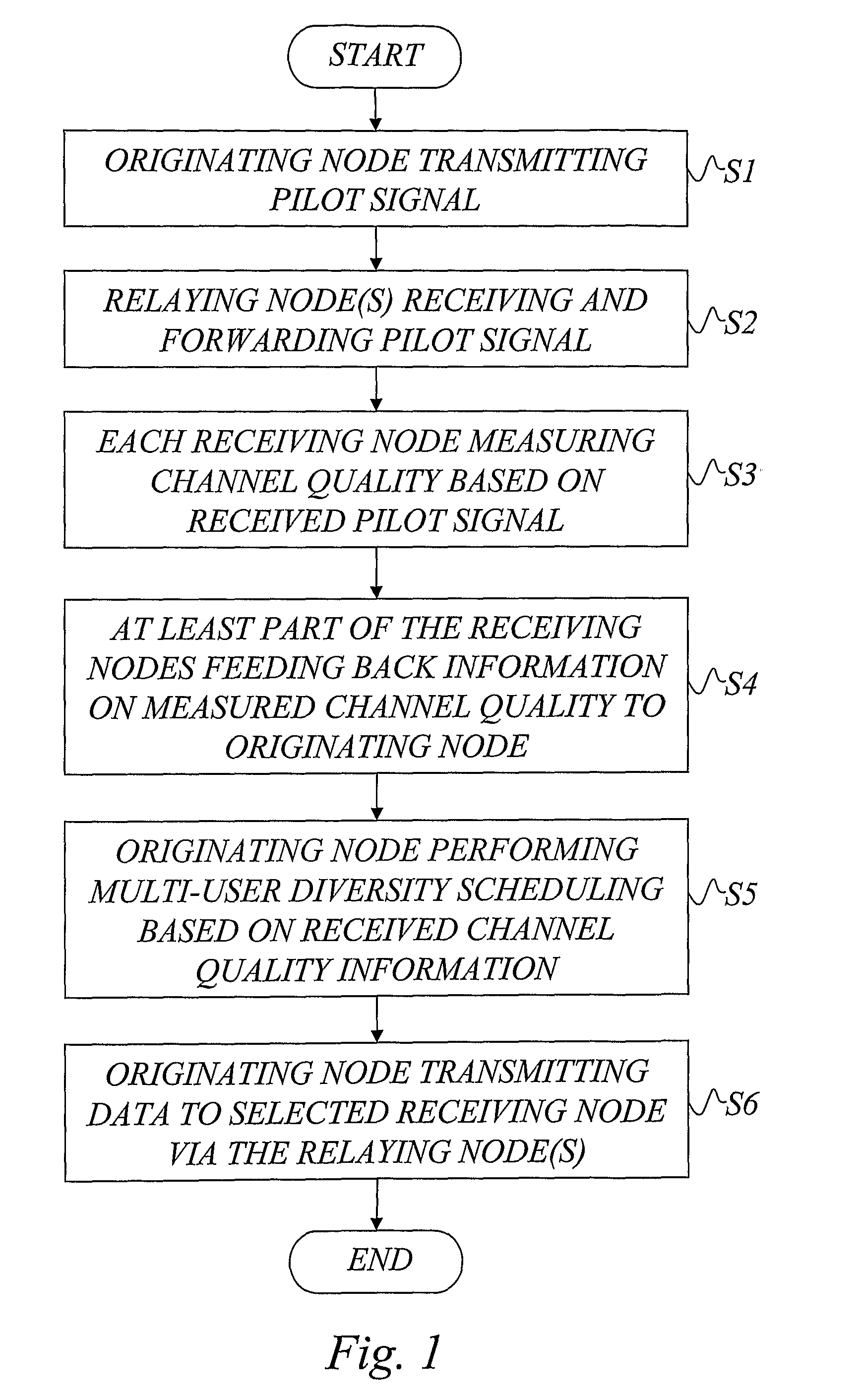
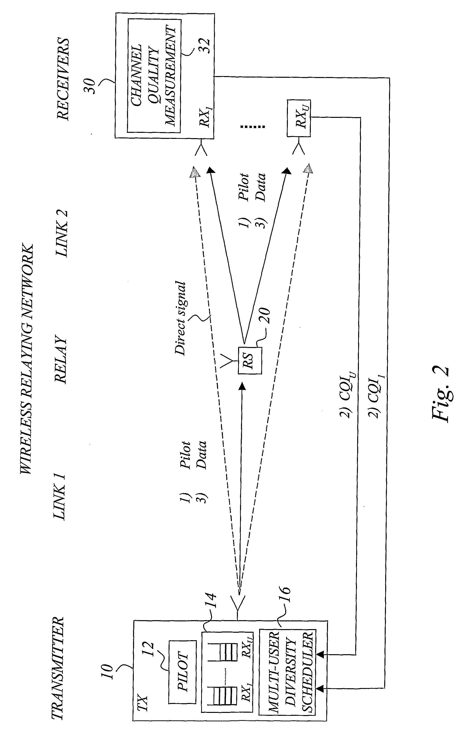
A wireless relaying network having a number of network nodes including a designated originating node, at least one relaying node, and at least two receiving nodes. The designated originating node transmits a pilot signal, and the relaying node(s) receives and forwards the pilot signal to the receiving nodes, each of which measures channel quality based on the received pilot signal. At least part of the receiving nodes feed information on the measured channel quality all the way back to the designated originating node, and the originating node then schedules data for transmission to at least one selected node of the receiving nodes based on the received channel quality information. Subsequently, the designated originating node transmits data to the selected receiving node(s) via the same relaying node(s) that forwarded the pilot signal. In this way, multi-user diversity scheduling is introduced to relaying networks that provides significant data rate enhancements.

Description

TECHNICAL FIELD OF THE INVENTION[0001]The present invention generally relates to wireless networks, and especially to wireless relaying networks such as cooperative relaying networks.BACKGROUND OF THE INVENTION[0002]Future wireless and / or cellular systems are expected, apart from many other aspects, to offer increased coverage, support higher data rates or a combination of both. In addition, the cost aspect of building and maintaining the system is expected to become even more important in the future. As data rates and / or communication distances are increased, the problem of increased battery consumption also needs to be addressed.[0003]One aspect is rethinking the topology used in existing systems, as there has been little change of topology over the three generations of cellular networks.[0004]For instance, it is well known that multi-hopping offers possibilities of significantly reduced path loss between communicating (relay) entities, which may benefit the user.[0005]Another typ...

Claims


Application Information

Patent Timeline
Patent Type & Authority Applications(United States)
IPC IPC(8): H04B7/14
CPCH04B7/15592H04L1/0003H04L1/0009H04L1/0026H04L5/0007H04L5/0035H04L5/0048H04L5/0057H04L2001/0097H04W40/28H04W52/40
Inventor LARSSON, PETER
Owner TELEFON AB LM ERICSSON (PUBL)
Why Eureka
Try Eureka