Determination of sound propagation speed in navigated surgeries

a technology of sound propagation speed and ultrasound wave, applied in the field of determining the speed of ultrasound wave, can solve the problems that the body structure that absorbs rather than reflects ultrasound wave, such as air-filled hollow spaces, is seldom useful as reflection parts, and achieves the effect of increasing the accuracy of scaling ultrasound imag

Inactive Publication Date: 2008-11-06
BRAINLAB
View PDF40 Cites 16 Cited by
  • Summary
  • Abstract
  • Description
  • Claims
  • Application Information

AI Technical Summary

Benefits of technology

[0022]A database may be provided that assigns different speeds of sound of the ultrasound waves for propagation through different types of parts of the body structure (for example, blood or tissue). When the different types of body structure are identified and their positions and arrangement is determined using NMR, a corresponding speed of sound may be assigned to the individual types. It is then possible to determine a spatial distribution of the speed of ultrasound waves throughout the body structure. This spatial distribution may be calibrated by determining the speed of ultrasound waves in accordance with the invention. The calibration may be configured such that the mean speed of sound through the body structure is adapted to the speed of sound determined in accordance with the invention. This process may be performed such that a mean speed of sound (based on the database: a “database speed of sound”) is determined. This determination may be made along the sound path from the stored spatial distribution data and the medical analysis. The value determined may be compared with the speed of sound calculated (“measured mean speed of sound”) in accordance with the invention, that represents a mean value along the measurement path. The speed-of-sound values for the individual regions of the body structure that are stored in the database may be raised or lowered by a particular percentage, until the mean database speed of sound corresponds to the measured mean speed of sound. In this manner, a calibrated spatial distribution of the speed of sound in the body structure is obtained. This spatial distribution may be used to increase the accuracy in scaling ultrasound images.

Problems solved by technology

A body structure that absorbs rather than reflects ultrasound waves, such as air-filled hollow spaces, are seldom useful as reflection parts.

Method used


Image

  • Determination of sound propagation speed in navigated surgeries
  • Determination of sound propagation speed in navigated surgeries
  • Determination of sound propagation speed in navigated surgeries

Examples


Embodiment Construction

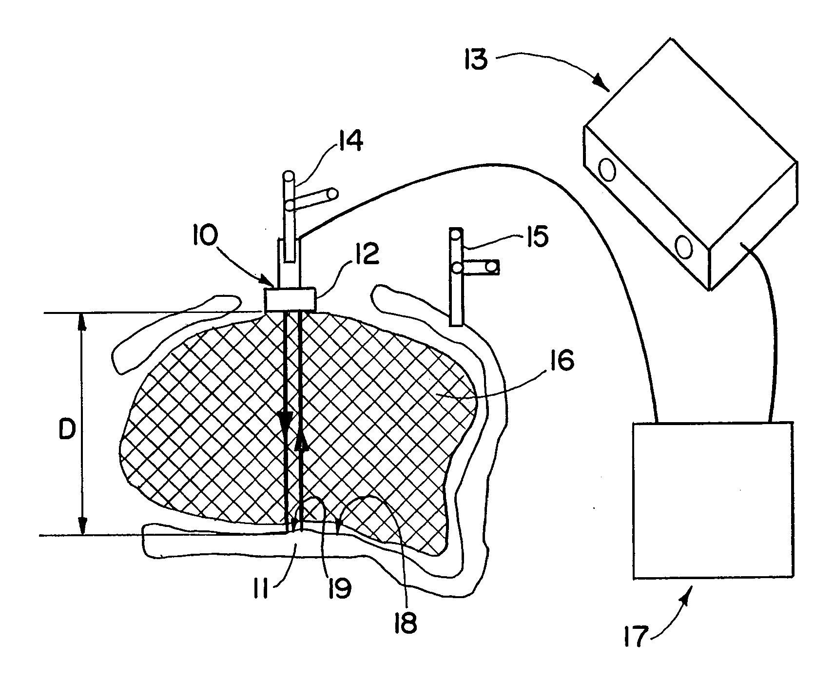
[0033]Methods and devices in accordance with the present invention enable the mean speed of sound in a body structure (for example, in a live brain or in other body structures) to be determined. The body structures can be homogeneous or heterogeneous. In the case of heterogeneous body structures, a method and device are disclosed that utilize data from medical analysis device (see above). In the following description, examinations of both homogeneous and heterogeneous body structures are discussed.

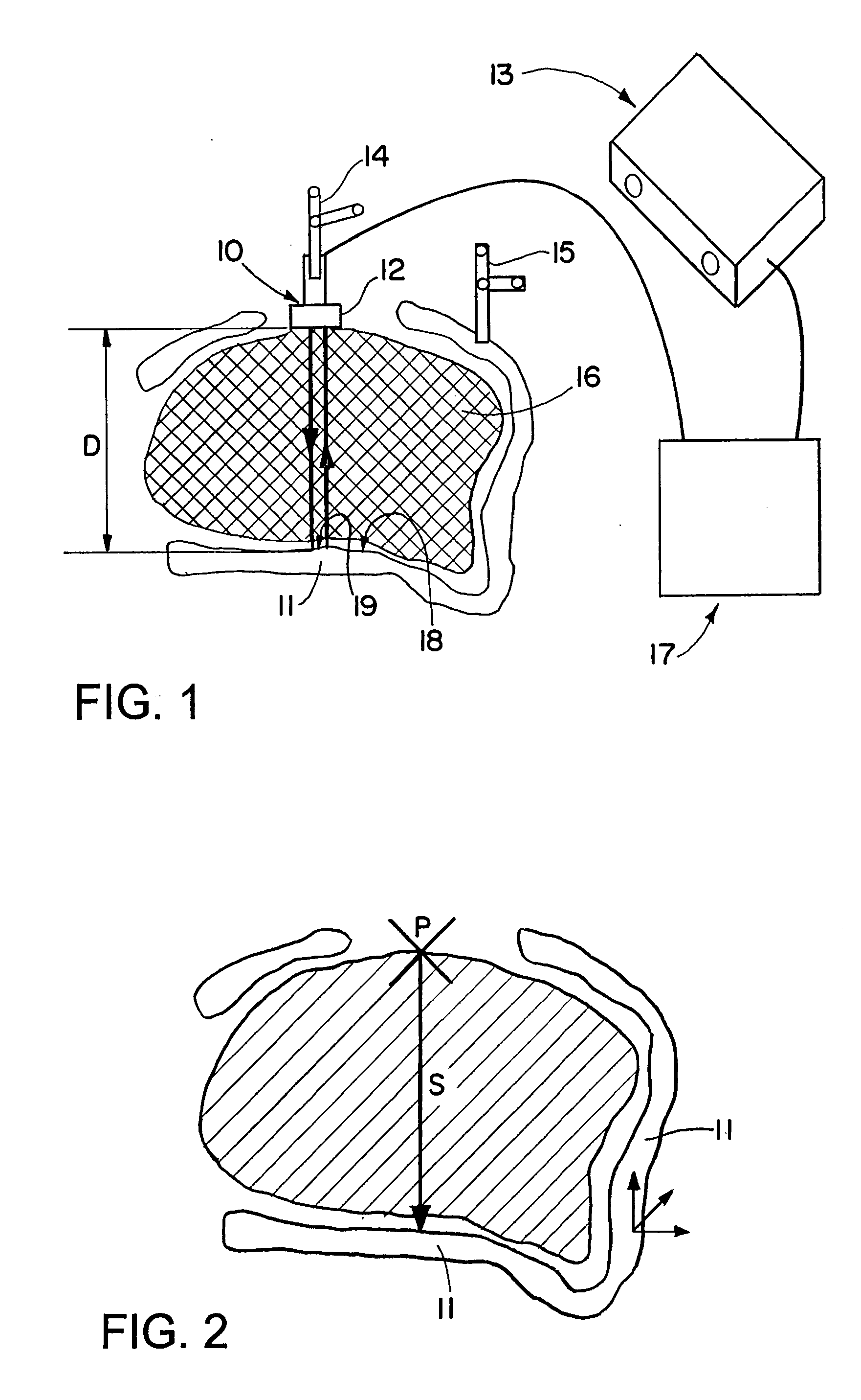
[0034]Homogeneous tissue may be bordered by a different type of body structure that differs with regard to its ultrasound propagation properties. This border leads to reflection. For example, the tissue could be partly surrounded by a bone, as is the case with the brain.

[0035]During sonographic examination, the position of a sonographic apparatus (in particular, the positions of transmitting or receiving ultrasound waves, or the position of an ultrasound probe) may be monitored using a nav...


PUM


Abstract

The patent discloses a method and device for measuring the speed of sound of ultrasound waves used in a sonographic examination of a patient's body structure. Marker devices are attached to an ultrasound probe and to an ultrasound reflecting body structure such that the distance traveled by the ultrasound waves can be determined by a navigation system. Using this distance and the transit time of the ultrasound waves, the measured speed can be calculated. The calculated speed of sound may then be used to accurately scale the ultrasound images.

Description

RELATED APPLICATION DATA[0001]This application claims priority of U.S. Provisional Application No. 60 / 917,143 filed on May 10, 2007, and EP 07107418 filed on May 3, 2007, which are incorporated herein by reference in their entirety.FIELD OF THE INVENTION[0002]The invention relates to determining the speed of ultrasound waves used for sonography (and echography) in an anatomical body structure in which propagation of the ultrasound waves occurs. The determined speed of the ultrasound waves may be used to increase the accuracy of an ultrasound examination conducted during a navigated surgery.BACKGROUND OF THE INVENTION[0003]In sonography, evaluating the measurement data (for example, scaling an ultrasound image) is often based on the assumption that the speed of sound is constant when passing through all body structures. Because determination of distances using sonography relies on the speed of sound, an incorrect assumption concerning the speed of sound can lead to incorrect distance...

Claims


Application Information

Patent Timeline
Patent Type & Authority Applications(United States)
IPC IPC(8): A61B8/00
CPCA61B8/0833A61B8/0875A61B8/4245A61B19/5244A61B2019/5255A61B2019/5276A61B2019/566A61B8/0808A61B34/20A61B2034/2055A61B2034/256A61B2090/378
Inventor THIEMANN, INGMARVOLLMER, FRITZ
Owner BRAINLAB
Why Eureka
Try Eureka