

Draper belt rib apparatus and method
- Summary
- Abstract
- Description
- Claims
- Application Information
AI Technical Summary
Benefits of technology
Problems solved by technology
Method used
Image

Examples
Embodiment Construction
[0021]The following description of the preferred embodiment(s) is merely exemplary in nature and is in no way intended to limit the invention, its application, or uses.
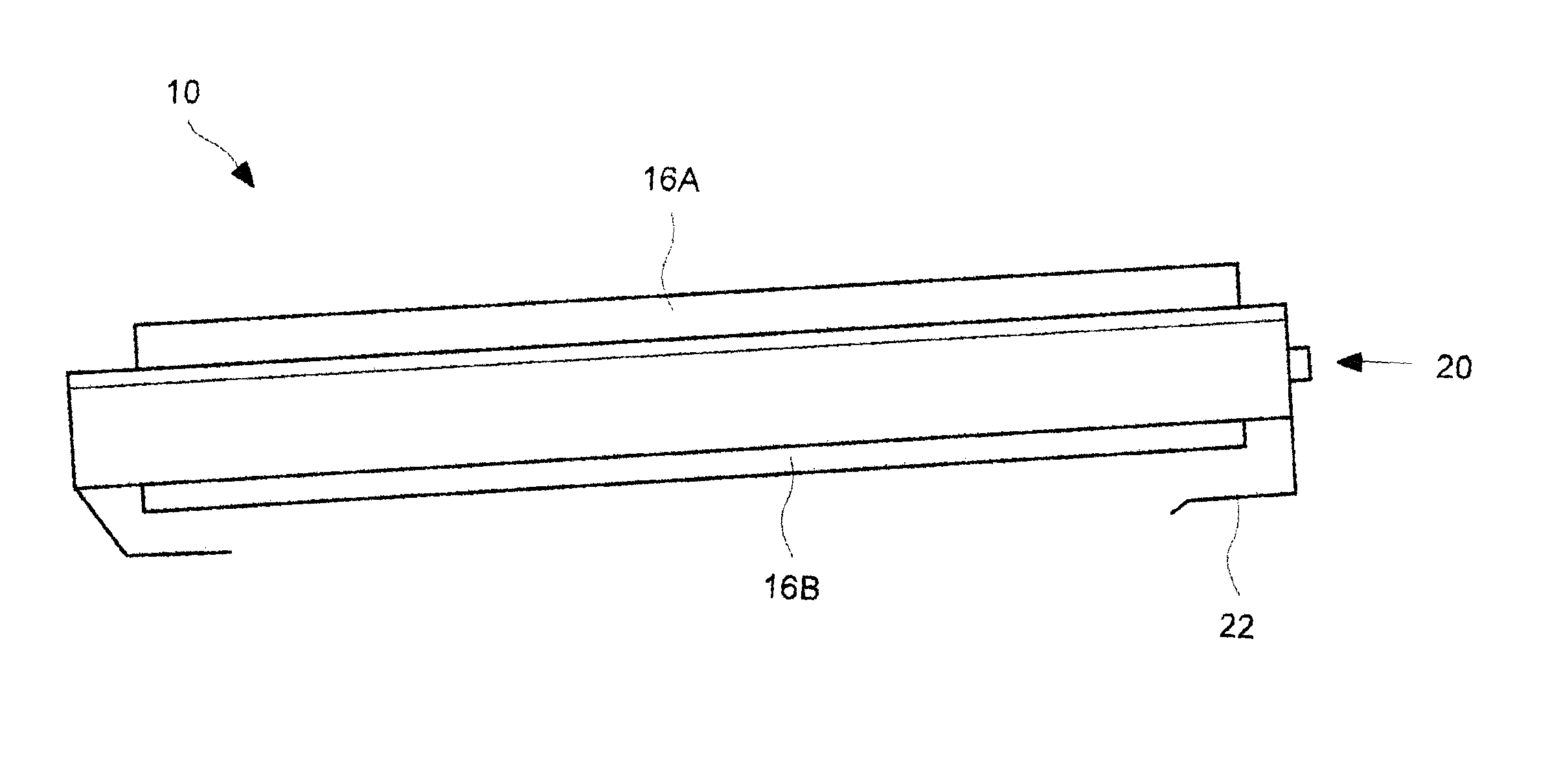
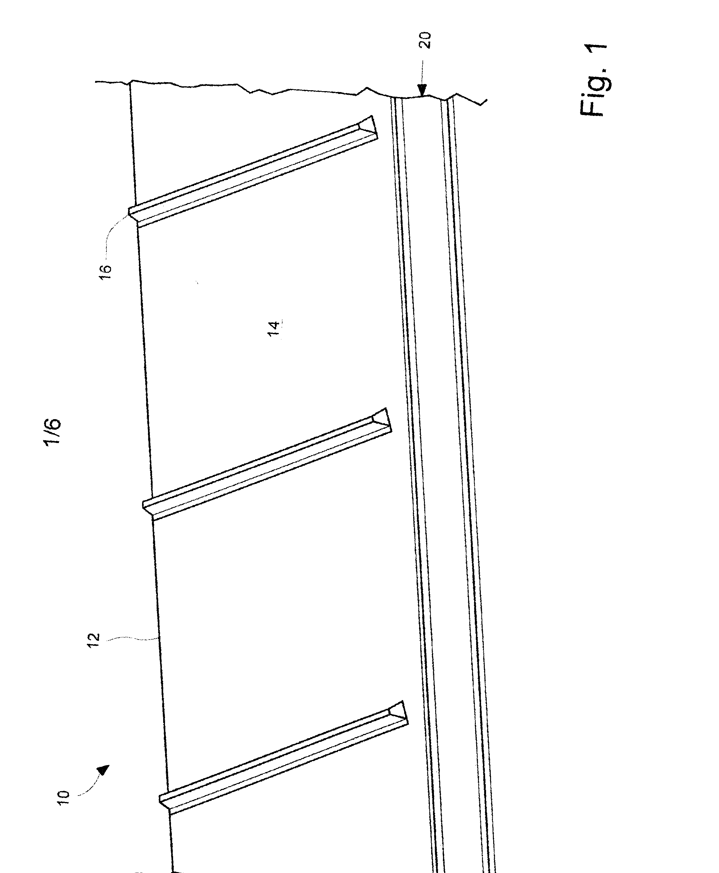
[0022]Referring now to the drawings in which like reference numbers indicate like elements, FIG. 1 is a perspective view of a draper conveyer belt 10. It includes a belt portion 12 having an outer surface 14. The belts are made of flexible material, commonly vulcanized rubber. Periodically spaced along the top surface 14 of belt 12 are ribs 16. In a combine draper header application, ribs 16 assist to convey cut crop laying on top surface 14 of the belt 12 towards a feeder house for continued processing.
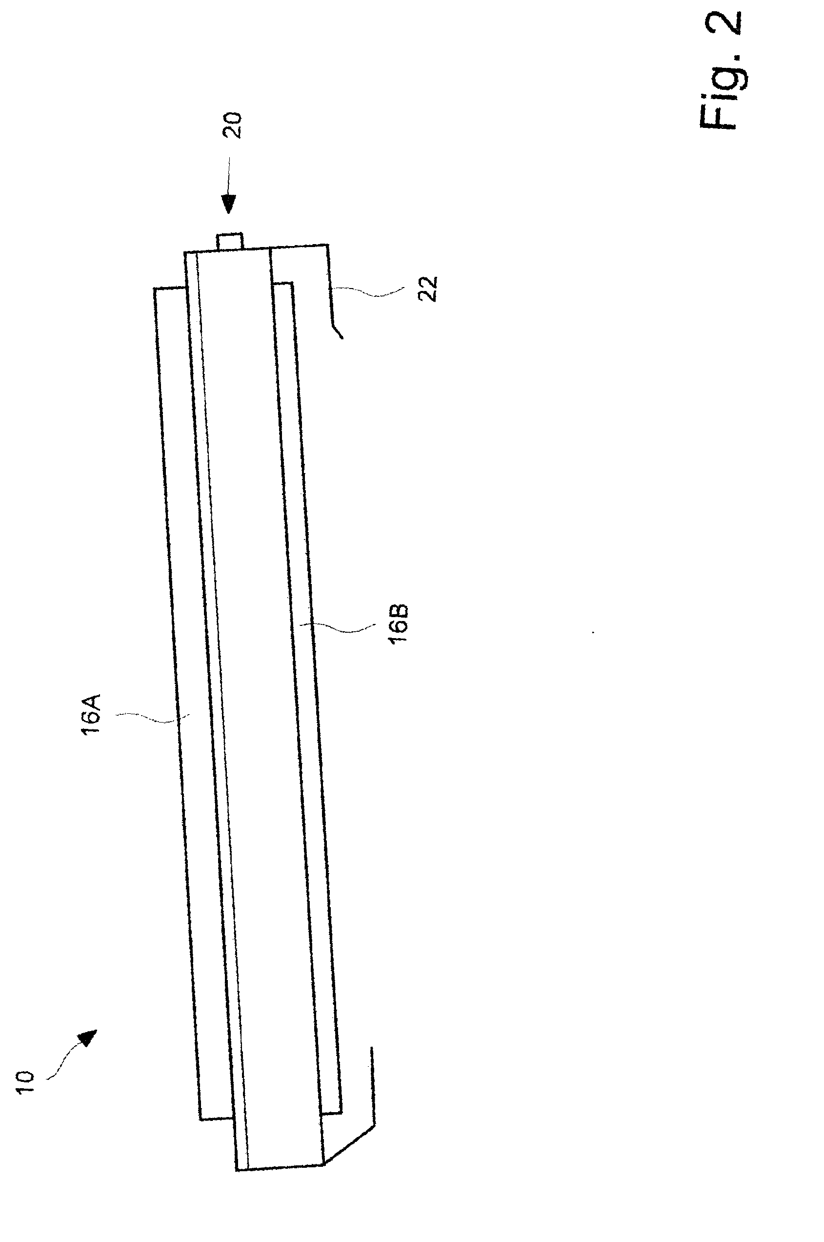
[0023]As seen in FIG. 2, the belt is supported by a belt support assembly 20. In a known manner, the ends of the belt 12 are supported by rollers. Typically, at least one of the rollers is a drive roller and the continuous loop belt 12 rolls around two end rollers and is supported in between by supports which may be co...
PUM
 Abstract
Description
Claims
Application Information