Refrigerant recovery apparatus with variable vacuum time and method

Active Publication Date: 2008-11-13
SPX CORP
View PDF63 Cites 34 Cited by
  • Summary
  • Abstract
  • Description
  • Claims
  • Application Information

AI Technical Summary

Benefits of technology

[0010]The foregoing needs are met, to a great extent, by the present invention, wherein in various aspects an apparatus, systems and methods are provided that in some embodiments include a variable period of time, rather than the fixed period of time for drawing down or evacu

Problems solved by technology

However, refrigerant recovery systems and methods that pull to a preset vacuum level, such as pulling to 0 psig with the compressor, and then running the vacuum pump in series with the compressor for the fixed period of time, do not take into consideration variations in ambient and vehicle temperature, as well as mobile AC system configuration differences, which can

Method used


Image

  • Refrigerant recovery apparatus with variable vacuum time and method
  • Refrigerant recovery apparatus with variable vacuum time and method
  • Refrigerant recovery apparatus with variable vacuum time and method

Examples


Embodiment Construction

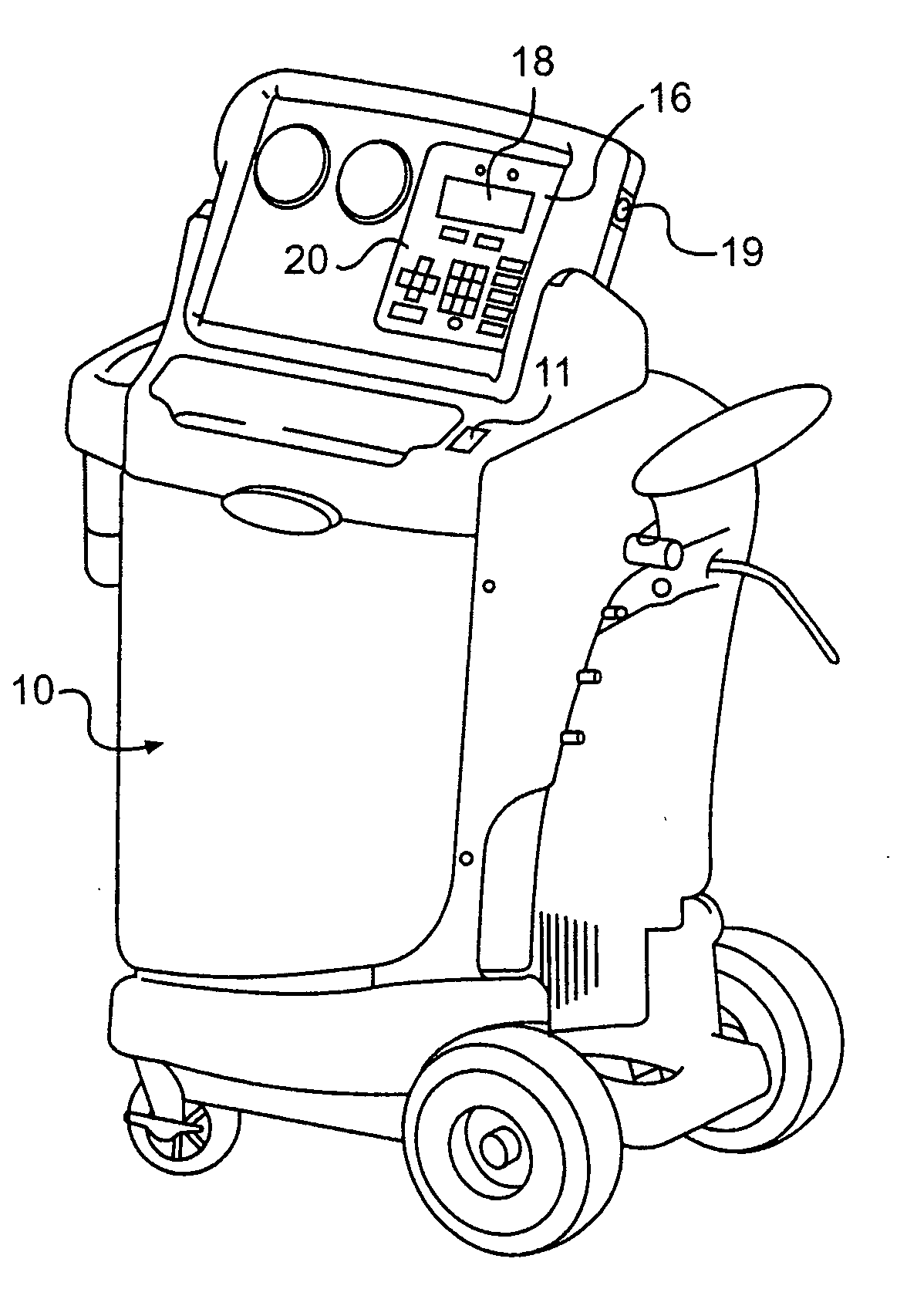
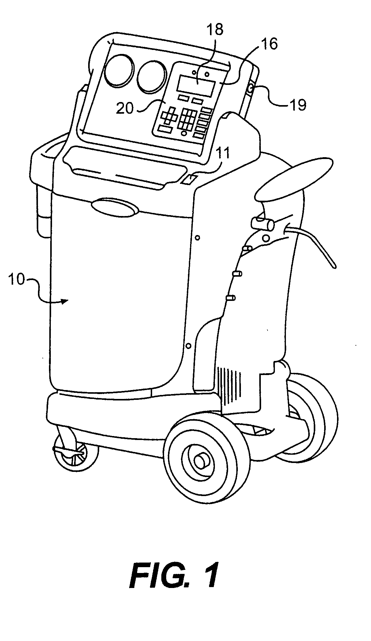
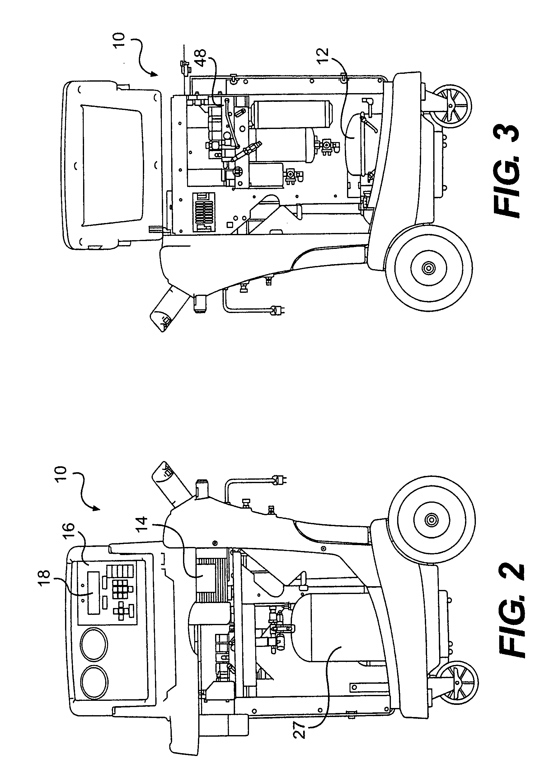
[0029]The invention will now be described with reference to the drawing figures, in which like reference numerals refer to like parts throughout. Various embodiments in accordance with the present invention provide a recovery apparatus, system and method that include a variable period of time during a second recovery stage, rather than a fixed period of time, for gas or liquid recovery, for drawing down or evacuating a vessel or system.

[0030]More particularly, and by way of example, the recovery apparatus, system and method that utilizes a variable period of time during a second recovery stage, rather than a fixed period of time, for gas or liquid recovery is described in relation to refrigerant recovery and to an AC recovery, recycling and recharging unit, although the present invention is not limited in this regard.

[0031]Exemplary embodiments for illustration of the present inventive recovery method, apparatus and system including a variable period of time to draw down or evacuate...


PUM


Abstract

A recovery apparatus, system and method, including a compressor to evacuate a gas or liquid from a system during a first phase and a second phase of a recovery process, and a vacuum pump to evacuate the gas or liquid during the second phase. A memory stores one or more correlation relations to determine a predetermined second variable recovery time for the second phase to evacuate the system to a second predetermined level related to a first recovery time to evacuate the vessel or system to a first predetermined level during the first phase, and a processor to determine the second variable recovery time, based on the one or more correlation relations and the first recovery time, and selectively control the compressor and the vacuum pump to evacuate the gas or liquid from the vessel or system to the first and second predetermined levels.

Description

FIELD OF THE INVENTION[0001]The present invention relates generally to refrigerant recovery apparatus and methods. More particularly, the present invention relates to refrigerant recovery methods and apparatus to provide enhanced recovery efficiency and a reduced service time for refrigerant collection by employing a variable vacuum time during the recovery process.BACKGROUND OF THE INVENTION[0002]Apparatus and systems used for air conditioning (AC) refrigerant recovery typically are required to meet a certain level of recovery efficiency. The need to provide for recovery efficiency is important to reduce emissions of refrigerant during the recovery process and to provide for accurate recharging, such as for mobile AC systems.[0003]A SAE Surface Vehicle Standard has been issued, SAE J2788, in December of 2006. This SAE standard implements a refrigerant recovery standard for mobile AC systems to achieve a 95% refrigerant recovery efficiency in 30 minutes or less, based upon a 3 lb ca...

Claims


Application Information

Patent Timeline
IPC IPC(8): F25B45/00
CPCB60H1/00585F25B45/00F25B2345/0052
Inventor BROWN, WILLIAMMURRAY, GARY
Owner SPX CORP
Why Eureka
Try Eureka