Hybrid Thermal Energy Conversion for HCCI Heated Intake Charge System

a technology of thermal energy conversion and heated intake charge, which is applied in the direction of hybrid vehicles, electrical control, combustion air/fuel air treatment, etc., can solve the problems of reducing the thermal energy availability of heating the intake charge, unable to provide sufficient heat or sufficiently precise temperature control, and/or the above heat source may be unavailable and/or insufficient heat or sufficient temperature control, etc., to achieve accurate temperature control of the intake charge, reduce the impact of fuel economy, and harvest various sources of thermal energy

Inactive Publication Date: 2008-11-13
FORD GLOBAL TECH LLC
View PDF9 Cites 72 Cited by
  • Summary
  • Abstract
  • Description
  • Claims
  • Application Information

AI Technical Summary

Benefits of technology

[0006]By providing a thermal management system for a HCCI-electric engine that harvests various sources of thermal energy and / or excessive or waste electric power, it may be possible to provide the additional heating and more accurate intake charge temperature control with reduced impact on fuel economy. In particular, by providing a thermal management system for a hybrid HCCI-electric engine that utilize various thermal energy and / or electrical power, it may be possible to operate the HCCI engine efficiently, even under conditions such as when the engine is used to charge the battery while the vehicle is parked.

Problems solved by technology

However, the inventor herein has recognized that under certain circumstances, the above heat sources may be unavailable and / or unable to provide sufficient heat or sufficiently precise temperature control.
For example, during engine cold start or idle, or when the engine is operated to charge the battery while the vehicle is parked, sufficient heat may be unavailable from the exhaust and / or the engine to heat intake air / charge.
This may be especially true in hybrid vehicle configurations, where the reduced engine size and increased engine efficiency in HCCI-electric hybrid engines further decrease thermal energy availability for heating the intake charge.
While burners and heaters have been used to provide the additional heating needed for the intake charge (see, for example, U.S. Pat. No. 6,295,973 which describes an electrical heater installed at the intake air port for heating the intake air), such an approach may consume electricity and reduce fuel efficiency.

Method used


Image

  • Hybrid Thermal Energy Conversion for HCCI Heated Intake Charge System
  • Hybrid Thermal Energy Conversion for HCCI Heated Intake Charge System
  • Hybrid Thermal Energy Conversion for HCCI Heated Intake Charge System

Examples


Embodiment Construction

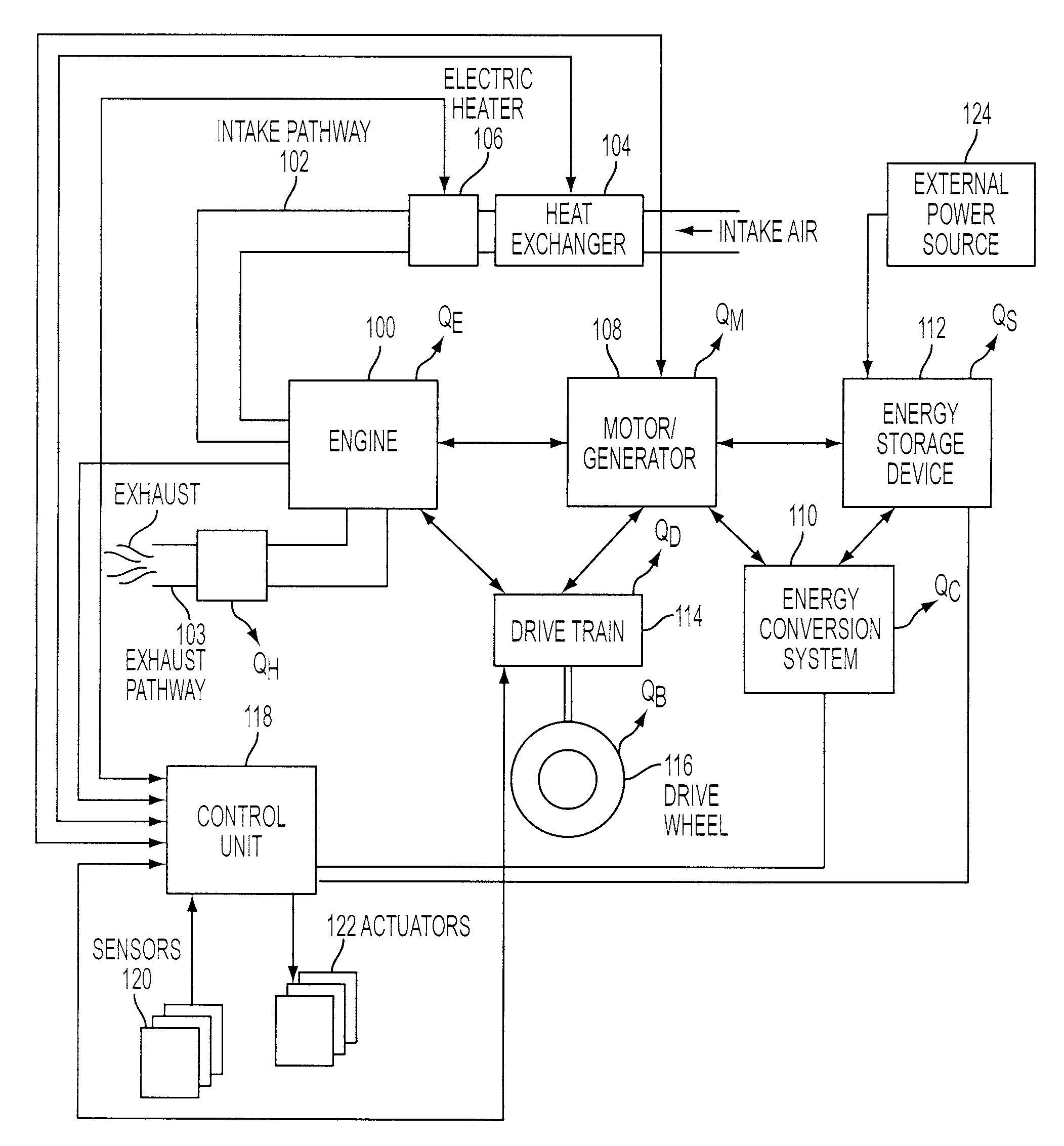
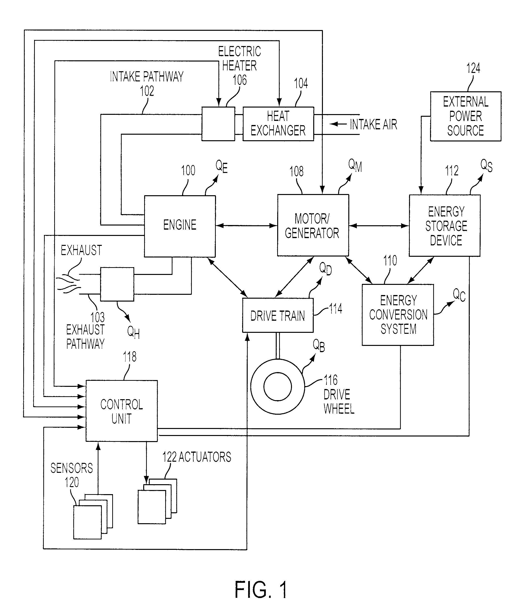
[0016]FIG. 1 is a block diagram illustrating an example intake thermal management system for a HCCI engine, which may include an engine 100 with an intake pathway 102 and an exhaust pathway 103, a heat exchanger 104 that harvests vehicle thermal energy to heat intake air, and an electric heater 106. The intake thermal management system may include an electric power system for a hybrid power train (not labeled), which may include a motor / generator 108 for generating electrical power from engine torque as part of an engine electrical power generating system (not all shown) and / or regenerative braking as part of an regenerative braking system (not all shown), an energy conversion system 110, an energy storage device 112. The intake thermal management system may also include a drive train 114 and a set of drive wheels 116. The energy storage device 112 may be coupled to an external power source 124 for supplying power used for charging the energy storage device. The intake thermal manag...


PUM


Abstract

A method of operating an internal combustion engine coupled in a hybrid powertrain, the method comprising of extracting waste energy from a component of an electrical power system of the hybrid powertrain, and adjusting intake air temperature during homogeneous charge compression ignition operation of the engine by using said extracted waste energy.

Description

BACKGROUND AND SUMMARY[0001]Engines may operate with various forms of combustion, one of which is Homogeneous Charge Compression Ignition (HCCI), where an air and fuel mixture achieves a temperature where autoignition occurs without requiring a spark from a sparking device. Combustion timing of HCCI engines may be controlled by regulation of the compression temperature of the charge, which in turn may be controlled by regulating the intake charge temperature (temperature of intake charge just prior to compression).[0002]Various heat sources have been used to heat the charge as part of HCCI combustion control strategy, for example, heat generated from turbo charging the intake air, engine waste heat circulated by engine coolant, and / or waste heat harvested from the hot exhaust. However, the inventor herein has recognized that under certain circumstances, the above heat sources may be unavailable and / or unable to provide sufficient heat or sufficiently precise temperature control. For...

Claims


Application Information

Patent Timeline
Patent Type & Authority Applications(United States)
IPC IPC(8): F02B29/00F02D41/00
CPCY02T10/7005Y02T10/7077B60K6/442B60K6/46B60L7/14B60L11/123B60L11/14B60W10/06B60W10/08B60W10/24B60W10/26B60W20/00B60W2510/244F02B1/12F02B29/0418F02D29/02F02D33/02F02D41/068F02D41/3035F02M25/0707F02M25/0727F02M31/08F02M31/107F02M31/13F02M31/14Y02T10/128Y02T10/146Y02T10/6217Y02T10/6234Y02T10/6269Y02T10/6286Y02T10/126B60Y2400/435F02M26/05F02M26/23B60L50/61B60L50/16Y02T10/12Y02T10/62Y02T10/7072Y02T10/70B60W2510/24B60W20/40B60W2710/0688
Inventor ZUBECK, MICHAEL W.
Owner FORD GLOBAL TECH LLC
Why Eureka
Try Eureka