Integrated ignition coil and oil seal for head and cam cover

a technology of integrated ignition coil and oil seal, which is applied in the direction of ignition sparking plugs, other installations, induction energy storage installations, etc., can solve the problems of inconvenient installation, inconvenient installation, and inability to meet the needs of the engine compartment, so as to reduce the weight and cost, increase the interior space, and free up valuable space

Inactive Publication Date: 2008-11-13
DELPHI TECH INC
View PDF17 Cites 15 Cited by
  • Summary
  • Abstract
  • Description
  • Claims
  • Application Information

AI Technical Summary

Benefits of technology

[0011]One advantage of the present invention is that it seals the spark plug from the lubricating oil, thus eliminating the need for a spark plug well (i.e., in the form of a press fit tube or otherwise), which decreases weight and cost, and frees up valuable space in the interior under the cam cover. As a consequence, another advantage is that the increased interior space may allow for the use of a pencil coil in certain situations instead of a plug top ignition coil. This arrangement also potentially eases packaging issues in an engine compartment that with conventional approaches a plug top coil would be needed but with the present invention a pencil coil can be used.
[0012]Additionally, the added space (e.g., 2-3 mm diameter under the cam cover) may be used for enlarging the ignition coil (e.g., increasing performance).
[0013]An ignition apparatus for an internal combustion engine having a cam cover enclosing engine valves, actuation therefor, and at least a spark plug engaged in a cylinder head includes an elongated transformer assembly, a case and a spark plug boot. The elongated transformer assembly is configured to generate a spark voltage and has a longitudinal axis. The case is configured to house the transformer assembly. The case includes a high-voltage...

Problems solved by technology

The spark plug well/press fit tube provides a barrier such that the spark plug is isolated from the lubricating oil, which if allowed to contact the spark plug or other energized portions of the ignition apparatus, could result in electrical shorts of the type which may result in misfire or other problems.
However, the tube is a separate component carrying with it a cost, size and weight penalt...

Method used


Image

  • Integrated ignition coil and oil seal for head and cam cover
  • Integrated ignition coil and oil seal for head and cam cover
  • Integrated ignition coil and oil seal for head and cam cover

Examples


case 34

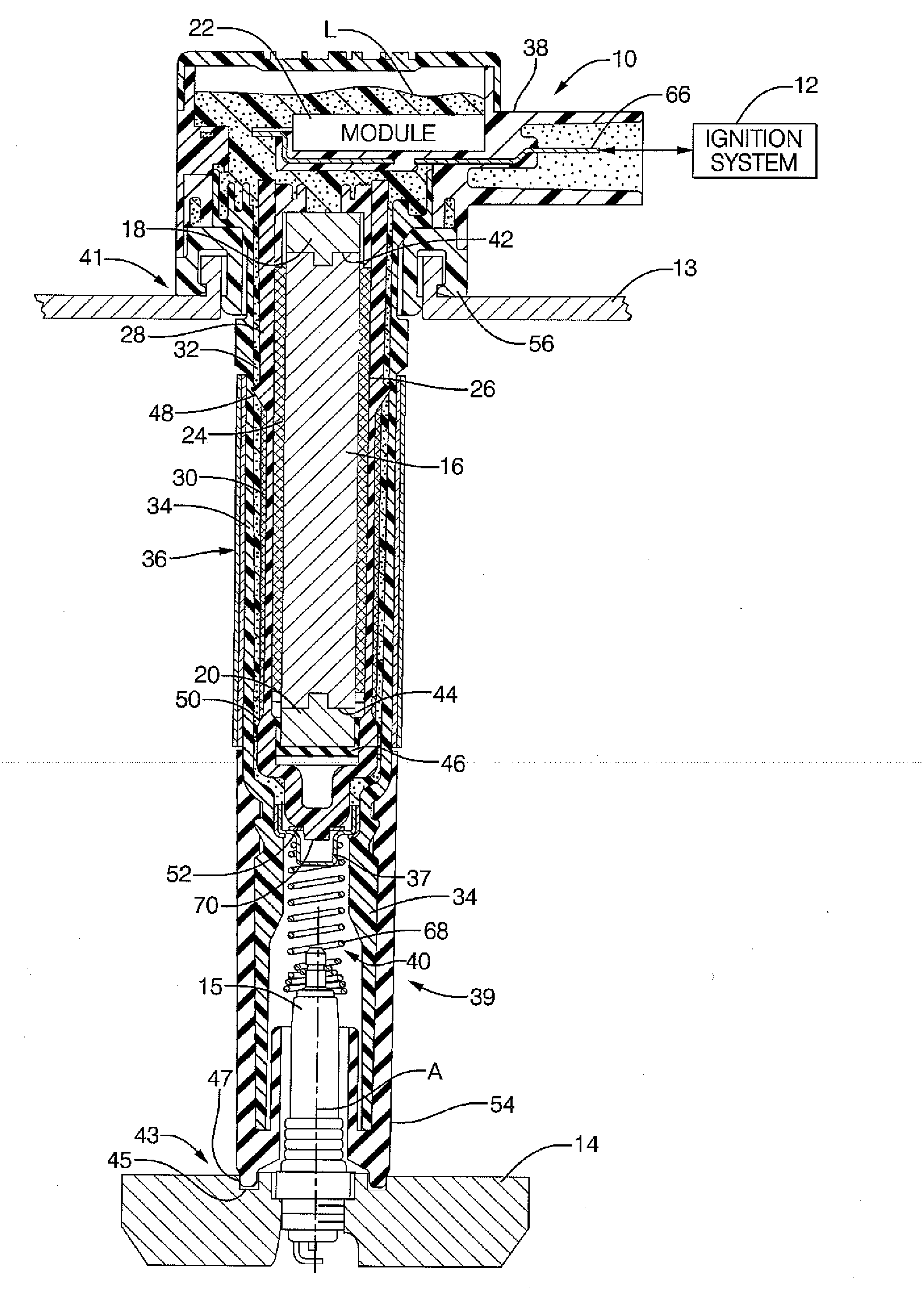
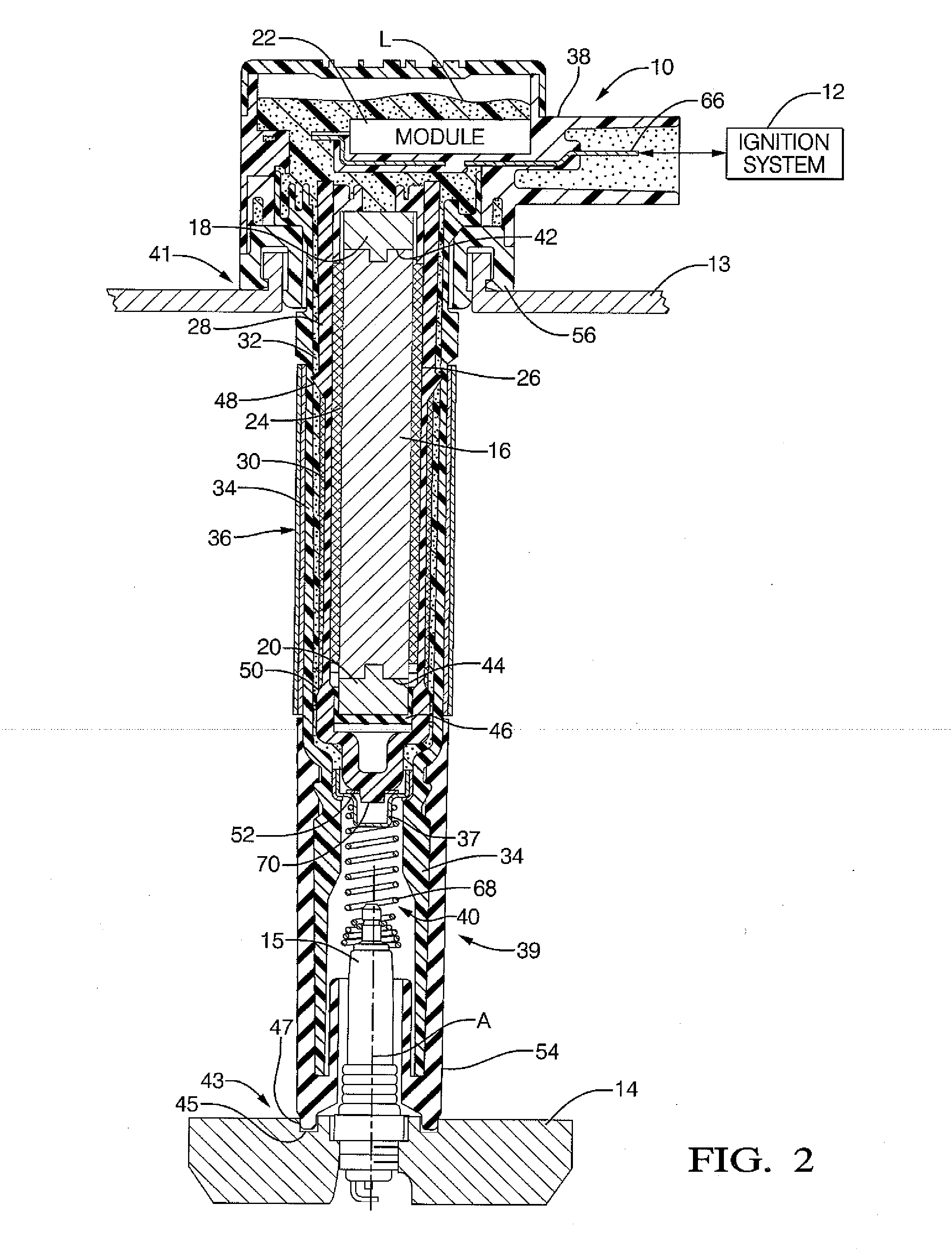
[0038]Case 34 includes an inner, generally enlarged cylindrical surface, an outer surface, a first annular shoulder, a flange, an upper through-bore, and a lower through bore.

[0039]The inner surface of case 34 is configured in size to receive and retain spool 28 which contains the core 16 and primary winding 24. The inner surface of case 34 may be slightly spaced from spool 28, particularly the annular spacing features 48, 50 thereof (as shown), or may engage the spacing features 48, 50.

[0040]A lower through bore of case 34 is defined by an inner surface thereof configured in size and shape (i.e., generally cylindrical) to provide a press fit with an outer surface of cup 37 at a lowermost portion thereof as described above. When the lowermost body portion of spool 28 is inserted in the lower bore containing cup 37, HV terminal 52 engages an inner surface of cup 37 (also via a press fit).

[0041]Case 34 is formed of electrical insulating material, and may comprise conventional material...


PUM


Abstract

An ignition apparatus includes an oil seal integrated with a spark plug boot and configured to mate with a cylinder head so as to seal the oil that is found under the cam cover from the spark plug and high voltage terminal of the plug. The cylinder head includes a ring-cavity recessed in the head surrounding the spark plug. The spark plug boot includes an annular sealing rib on a lowermost axial end. The sealing rib is configured in size and shape to effect an interference fit in the ring cavity. The ignition apparatus includes another seal integrated at the top to seal to the cam cover. The two integrated seals eliminate the need for a spark plug tube.

Description

BACKGROUND OF THE INVENTION[0001]1. Technical Field[0002]The present invention relates generally to an ignition apparatus or coil, and, more particularly, to an integrated ignition coil and oil seal for head and cam cover.[0003]2. Discussion of the Background Art[0004]Ignition coils utilize primary and secondary windings and a magnetic circuit. The magnetic circuit may include a central core formed of magnetically-permeable material and a side core or shield, tubular in shape, formed of silicon steel, as seen by reference to U.S. Pat. No. 6,437,674 issued to Hamer et al. Hamer et al. further disclose an ignition coil having a relatively slender configuration adapted for mounting directly above a spark plug in a spark plug well-commonly referred to as a “pencil” coil.[0005]The spark plug well tube is typically very small in diameter, requiring that the conventional ignition coil, including the integral shield, fit inside. The spark plug well tube is conventionally formed of steel, bu...

Claims


Application Information

Patent Timeline
IPC IPC(8): F02P3/02
CPCF02P3/02F02P13/00
Inventor SKINNER, ALBERT A.HAMER, COLIN J.
Owner DELPHI TECH INC
Why Eureka
Try Eureka