Self-Pressurizing Supraglottic Airway

Active Publication Date: 2008-11-13
SALTER LABS LLC
View PDF64 Cites 31 Cited by
  • Summary
  • Abstract
  • Description
  • Claims
  • Application Information

AI Technical Summary

Benefits of technology

[0019]Depending on the embodiment of the system the alteration of pressure in the inner volume of the sealing ring may alter the size of the sealing ring as ai

Problems solved by technology

In particular, the use of inflated structures or semi-rigid plastic constructs to hold the device in place in the throat can lead to undesirable pressure on throat tissue.
While the structure of these devices are generally made pliable and soft so as to minimize potential damage from their near constant contact with throat tissues, the constant pressure they impart on potentially sensitive structures in the throat ca

Method used


Image

  • Self-Pressurizing Supraglottic Airway
  • Self-Pressurizing Supraglottic Airway
  • Self-Pressurizing Supraglottic Airway

Examples


Embodiment Construction

)

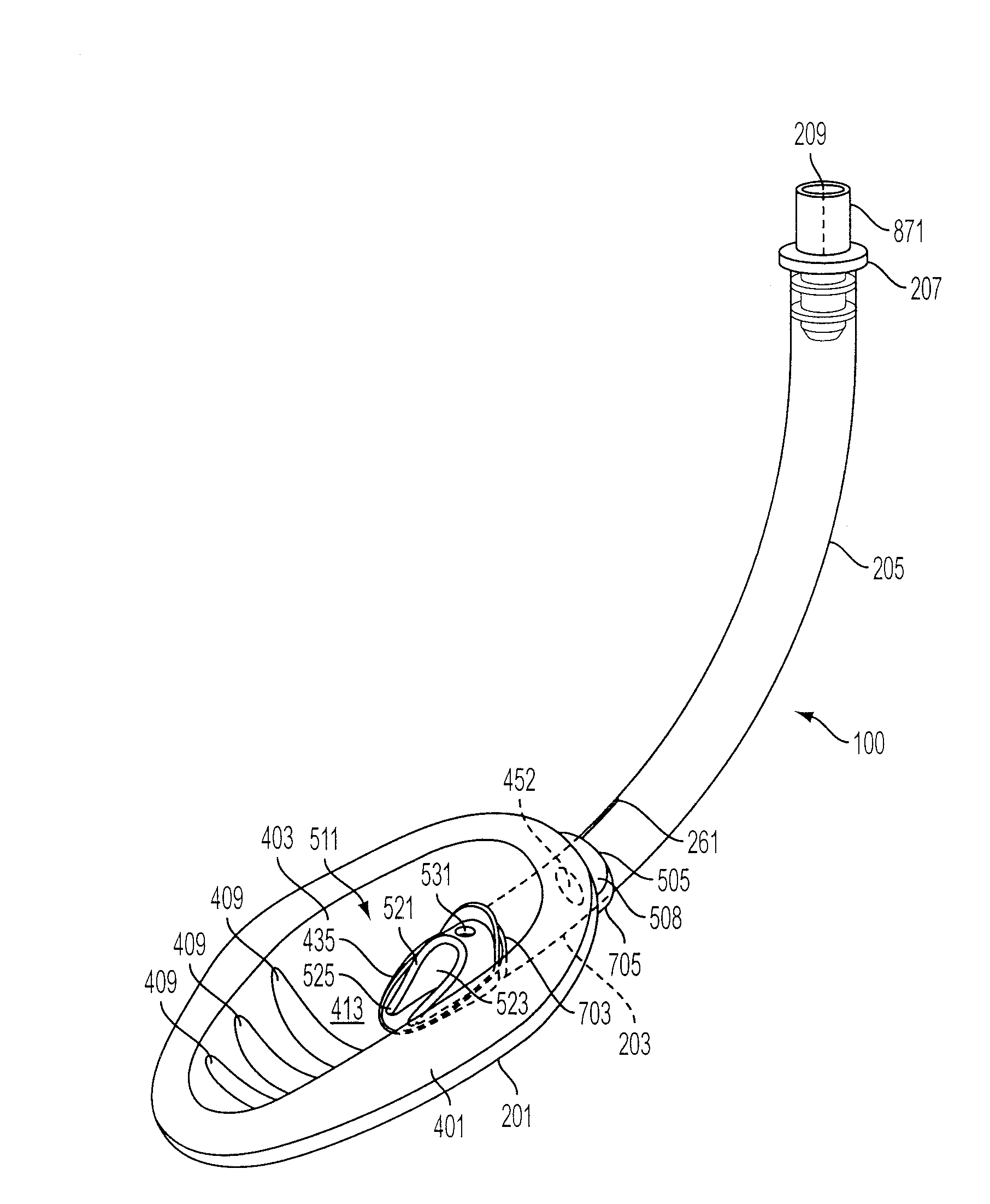
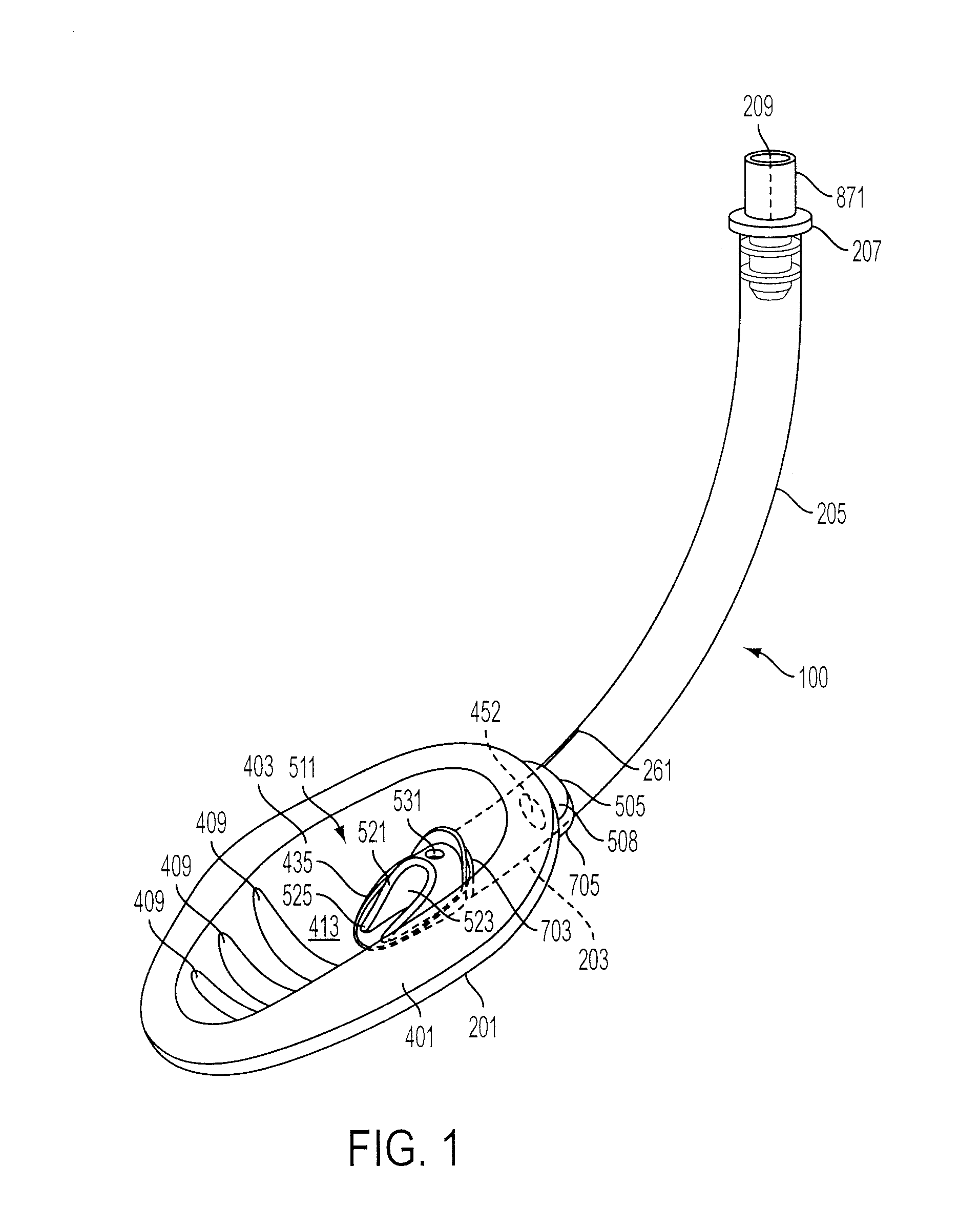
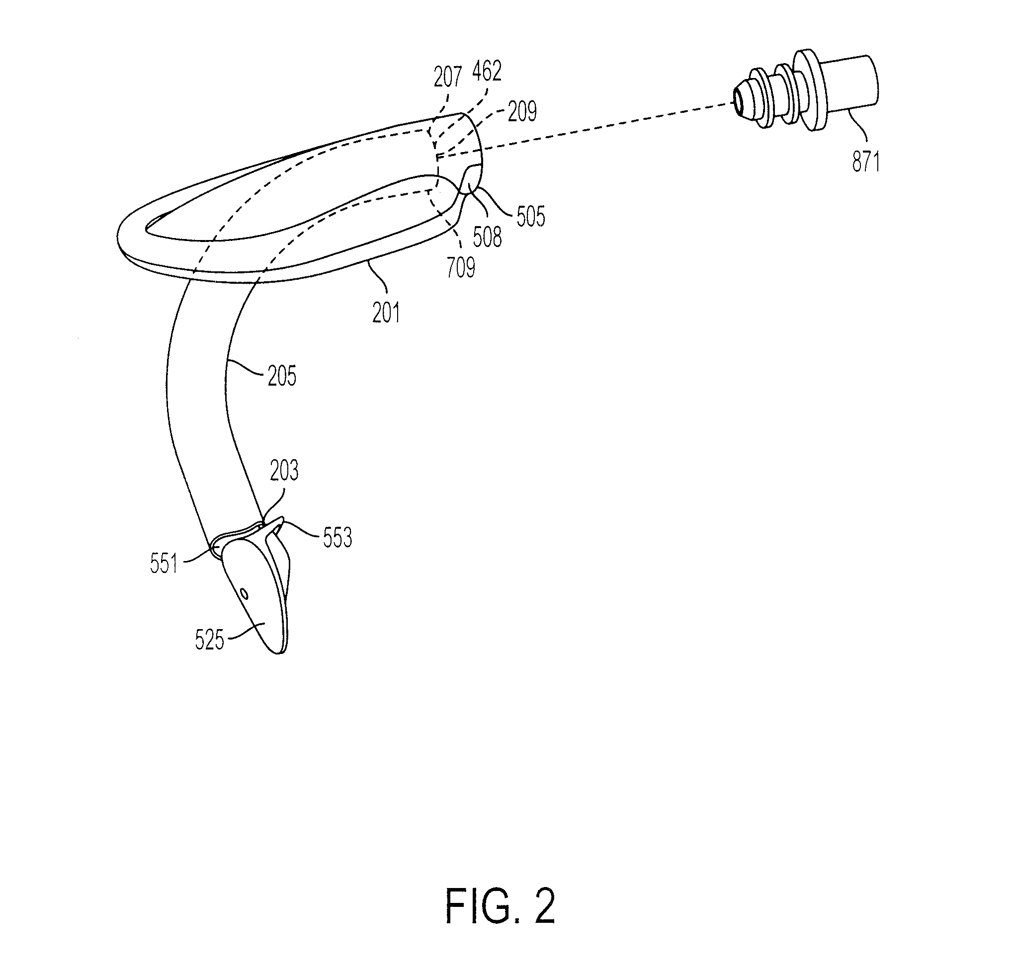
[0032]The following detailed description illustrates by way of example and not by way of limitation. Described herein, among other things, is an embodiment of a supraglottic airway which includes a shield for sealing with the larynx which is designed to exert greater pressure, and therefore a stronger seal, when an assisted inhalation is being provided for the patient during positive-pressure ventilation. Specifically, the supraglottic airway has a shield (201) including a sealing ring (401). The ring (401) is in gaseous (or more generally fluid) communication with the airway path through which artificial respiration air is provided to the patient. While the supraglottic airway described herein incorporates certain features in the shape and arrangement of the shield (201) for improved placement in the airway, it should be recognized that these features are not required and the sealing rings (401) and related structures discussed herein can be used on airways of other shapes and for...


PUM


Abstract

A supraglottic airway of the type used to facilitate lung ventilation and the insertion of endo-tracheal tubes or related medical instruments through a patient's laryngeal opening where the shield is designed to have an internal increase in pressure during assisted inhalation such as positive-pressure ventilation.

Description

BACKGROUND[0001]1. Field of the Invention[0002]The invention relates to an artificial airway device, more specifically to a supraglottic airway designed to have increased internal pressure during introduction of artificial positive-pressure ventilation.[0003]2. Description of the Related Art[0004]In general, supraglottic airways such as laryngeal masks allowing for both rapid lung ventilation and the insertion of medical instruments and tubes into the laryngeal openings of patients have been described in patents, such as U.S. Pat. No. 4,509,514 to Brain and U.S. Pat. Nos. 6,422,239 and 5,937,860 to Cook the entire disclosures of which were herein incorporated by reference. Laryngeal masks generally consist of two major components, a breathing tube and an inflatable or rigid shield, these devices are inserted into a patient's throat, and when properly positioned, cover the laryngeal opening. A seal is then formed around the circumference of the laryngeal opening by the inflation of a...

Claims


Application Information

Patent Timeline
IPC IPC(8): A61M16/04
CPCA61M16/04A61M16/0816A61M16/0409A61M16/0434A61M16/0057A61M16/045A61M16/0447A61M2207/10
Inventor COOK, DANIEL J.
Owner SALTER LABS LLC
Why Eureka
Try Eureka