Gas Sensor

Inactive Publication Date: 2008-11-13
ROBERT BOSCH GMBH
View PDF1 Cites 4 Cited by
  • Summary
  • Abstract
  • Description
  • Claims
  • Application Information

AI Technical Summary

Benefits of technology

[0006]The gas sensor according to the present invention has the advantage over the related art that at the same heat output the sensor element is heated to approximately the same temperature. It is intended for this purpose that the absorptivity of the protecting tube is subject to only minor changes after start of operation of the gas sensor. A minor change in the absorptivity of the protecting tube is to be understood within the scope of this application to be a change of 30% maximum. It has been proven that the absorptivity of the protecting tube has a surprisingly large effect on the relationship between the heat output of the heater and the temperature of the sensor element in the areas heated by the heater.
[0007]In a gas sensor according to the present invention, the temperature of the sensor element at the same heat output and the same operating conditions is largely independent from the state of the surface of the protecting tube. This makes it possible to heat the sensor element to the setpoint temperature even under operating conditions where the regulation of the heater via the internal resistance of an electrochemical cell of the sensor element is not possible. Regulation of the heater via the internal resistance may be completely dispensed with in certain applications.

Problems solved by technology

However, this has the disadvantage that a protecting tube having high absorptivity needs a greater heat output for reaching a predefined temperature of the sensor element than a protecting tube having low absorptivity.

Method used


Image

  • Gas Sensor
  • Gas Sensor
  • Gas Sensor

Examples


Embodiment Construction

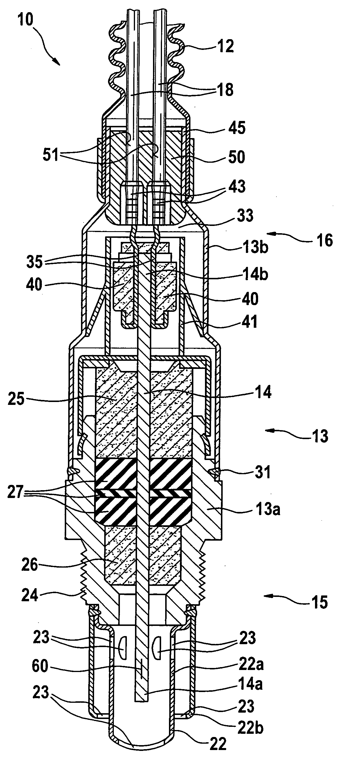
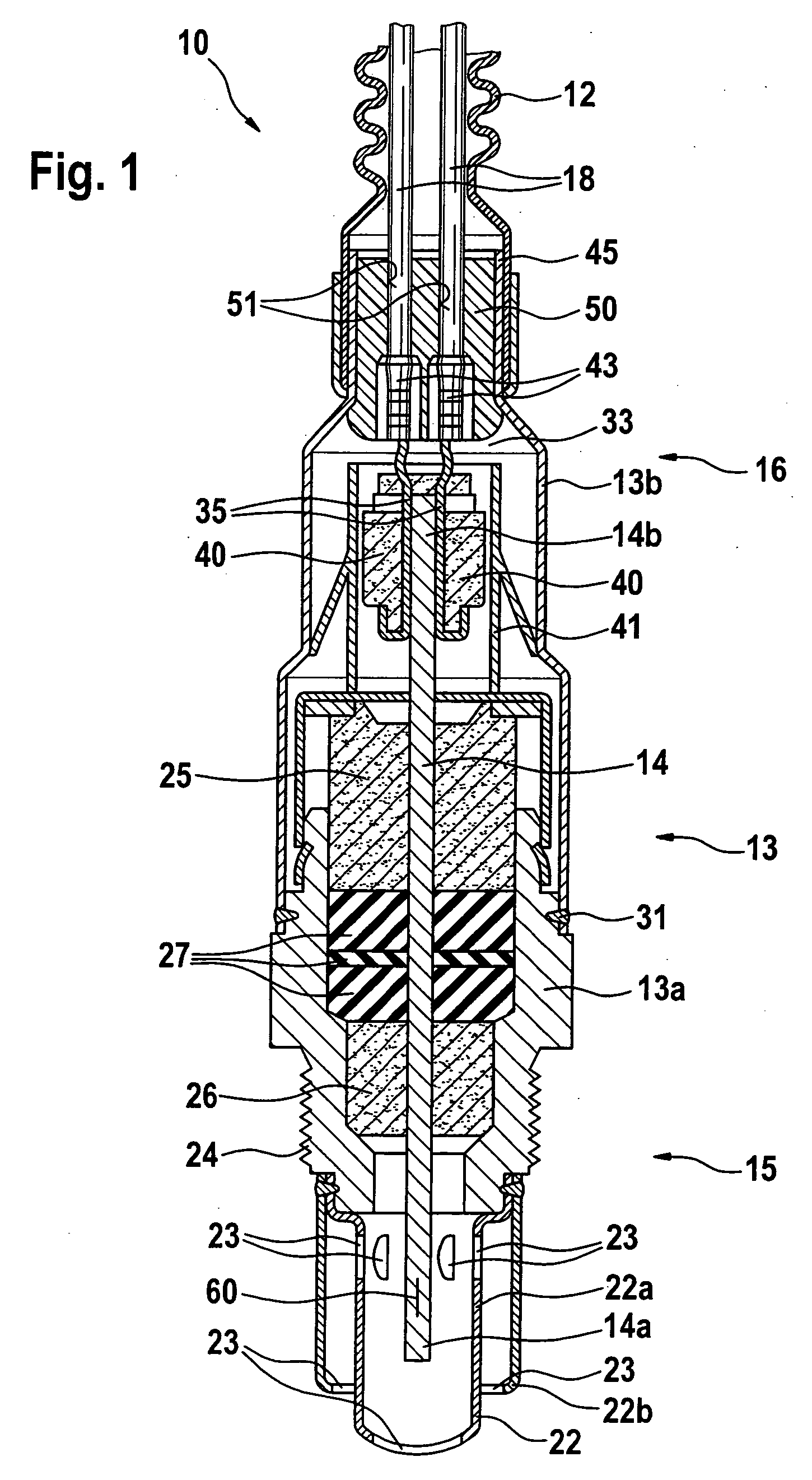
[0016]FIG. 1 shows a gas sensor 10, e.g., a lambda sensor or a broadband lambda sensor for detecting the oxygen content in an exhaust gas of an internal combustion engine. Gas sensor 10 has a measuring-side section 15 and a connection-side section 16 and has a metallic housing 13 which is indicated in the measuring-side section denoted by reference numeral 13a and in the connection-side section 16 denoted by reference numeral 13b. A sensor element 14 is installed in a gas-tight manner in housing 13 using ceramic molded parts 25, 26 and a sealing element 27. In its connection-side section 16, gas sensor 10 is connected to a cable sheathing 12 in which connecting cables 18 for sensor element 14 are situated.

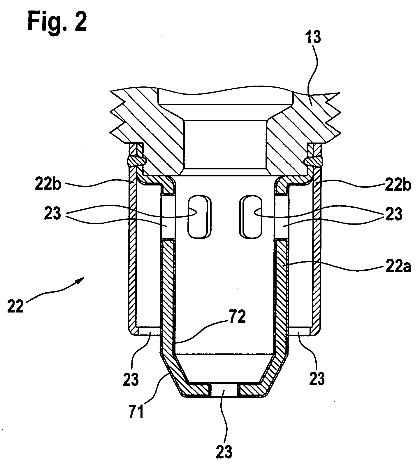
[0017]A protecting tube 22 is mounted on measuring-side section 13a of housing 13. Protecting tube 22 is double-walled and has an inner section 22a and an outer section 22b. Apertures 23 are introduced into protecting tube 22 which allow the gas to enter sensor element 14. Protecti...


PUM


Abstract

A gas sensor is used in particular for determining a physical property of a measuring gas, preferably for determining the concentration of a component of an exhaust gas in an exhaust branch of an internal combustion engine. The gas sensor has a sensor element situated in a housing. The housing includes a protecting tube having apertures through which the measuring gas may reach the sensor element. At least on its side facing the sensor element, the protecting tube has an absorptivity which is subject to only minor changes during the intended operation of the gas sensor in an exhaust branch of an internal combustion engine.

Description

BACKGROUND INFORMATION[0001]A gas sensor is described in German Patent Application No. DE 101 51 291, for example. The gas sensor is used for determining the oxygen concentration in the exhaust gas of an internal combustion engine. The gas sensor has a housing to which a protecting tube having apertures is attached. Through the apertures, the exhaust gas may reach a sensor element which is mounted in the housing in a gas-tight manner. The configuration of such a sensor element is generally known and is described, for example, in Automotive Electronics Handbook, Editor: Ronald K. Jurgen, Second Edition, McGraw-Hill, Inc. 1999. The sensor element includes one or multiple solid electrolyte sheets on which electrodes are situated. The electrodes and a section of a solid electrolyte sheet form one or multiple electrochemical cells. A heater is provided in a layer plane of the sensor element via which the sensor element and in particular the electrochemical cell are heated to a temperatur...

Claims


Application Information

Patent Timeline
IPC IPC(8): G01N27/26G01N27/407
CPCG01N27/4077
Inventor WEYL, HELMUTTIEFENBACH, ANDY
Owner ROBERT BOSCH GMBH
Why Eureka
Try Eureka