Liquid Bridge and System

a liquid bridge and system technology, applied in the field of liquid bridge and system, can solve the problems of time-consuming manual procedure and inability to scale down in size of conventional scale devices to microfluidic scal

Active Publication Date: 2008-11-13
STOKES BIO LTD
View PDF4 Cites 40 Cited by
  • Summary
  • Abstract
  • Description
  • Claims
  • Application Information

AI Technical Summary

Benefits of technology

[0007]In this specification the term “droplet” is used to mean a small quantity or plug of liquid as it flows in an immiscible carrier liquid along a conduit.

Problems solved by technology

Simple scaling down in size of conventional scale devices to microfluidic scale is not a simple option.
Heretofore, handling of small quantities of liquids being transferred from one device or conduit to another often involves pipetting, which is a time-consuming manual procedure.

Method used


Image

  • Liquid Bridge and System
  • Liquid Bridge and System
  • Liquid Bridge and System

Examples


Embodiment Construction

Brief Description of the Drawings

[0053]The invention will be more clearly understood from the following description of some embodiments thereof, given by way of example only with reference to the accompanying drawings in which:—

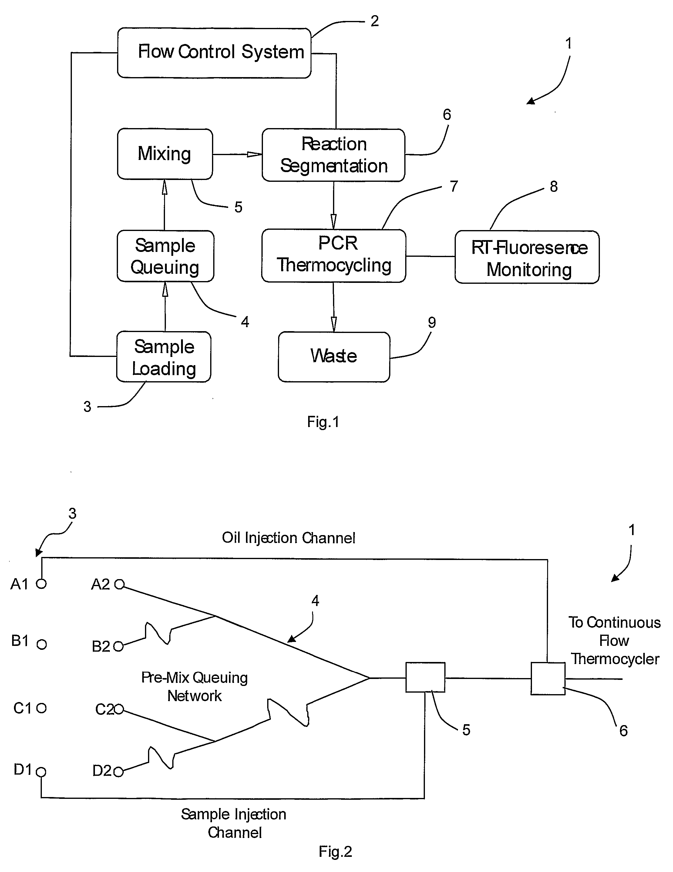
[0054]FIGS. 1 and 2 are schematic diagrams of a PCR preparation microfluidic system of the invention;

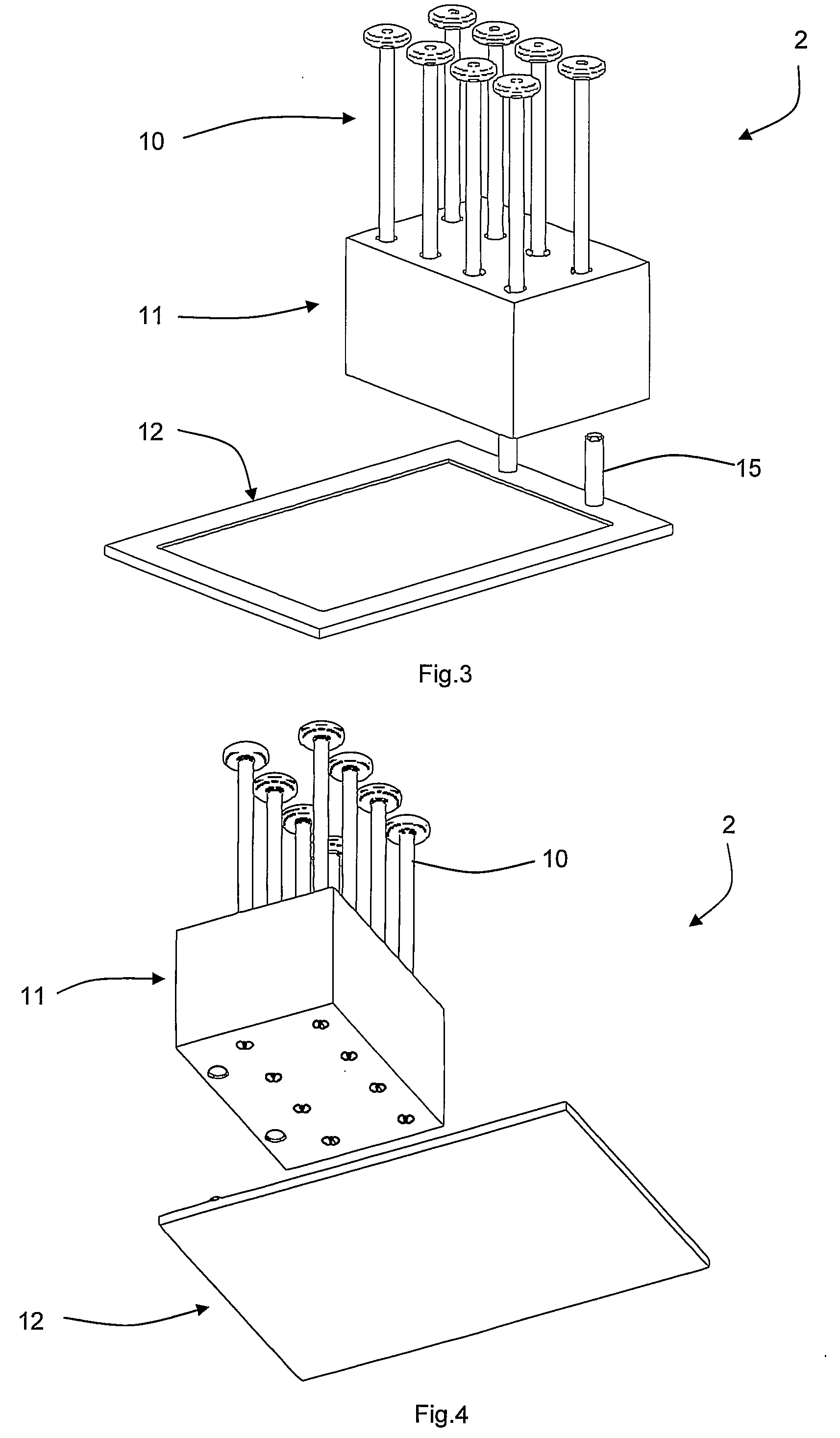
[0055]FIGS. 3 and 4 are above and beneath perspective views of a pumping system of the microfluidic system, and FIG. 5 is a cross-sectional diagram illustrating a sample well of the pumping system in more detail;

[0056]FIG. 6 is a sequence of diagrams A to G illustrating operation of a mixing bridge incorporating a funicular bridge;

[0057]FIG. 7 is a diagram showing internal circulation and the protective oil film around a micro-reactor droplet;

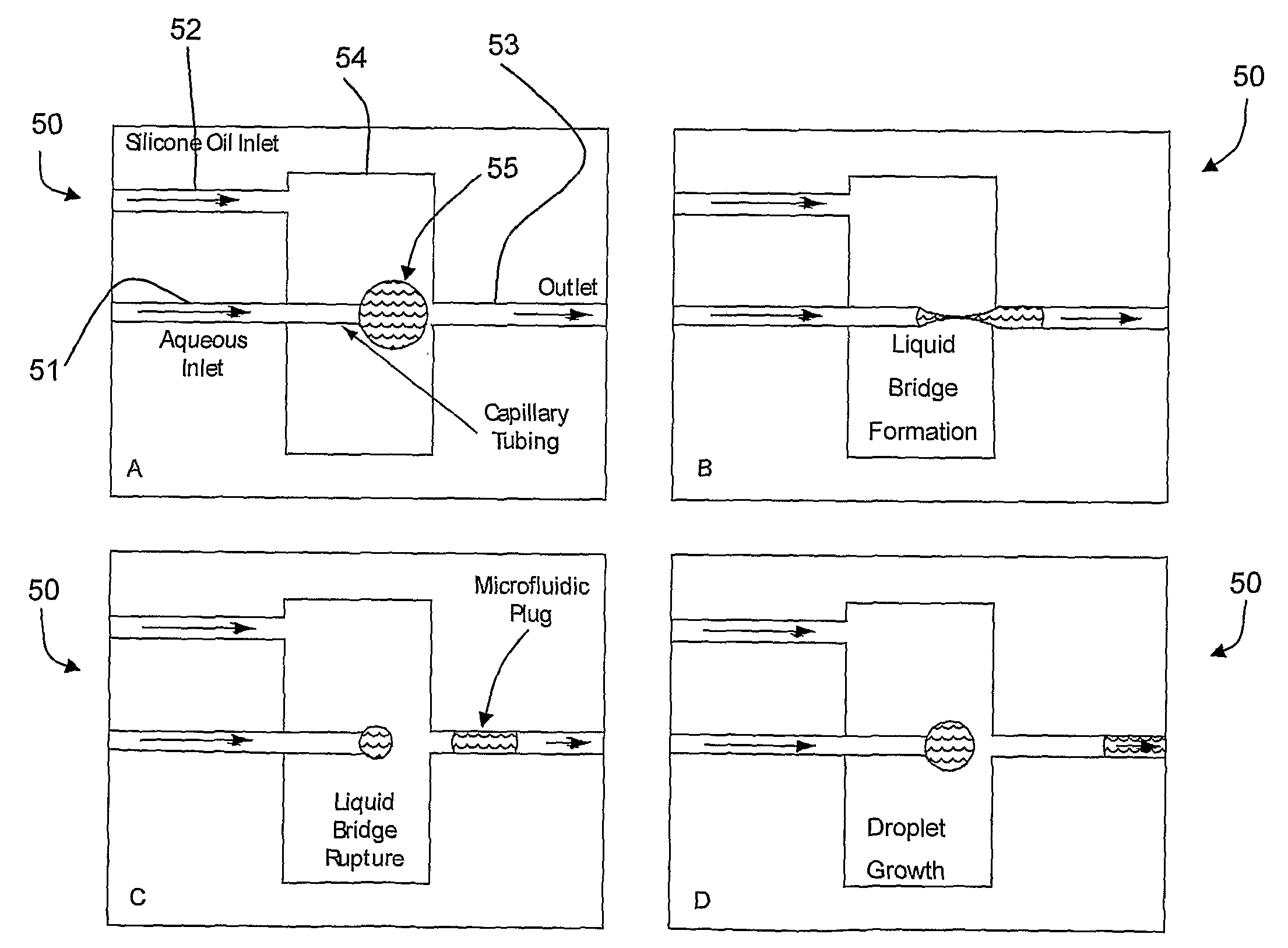
[0058]FIG. 8 is a sequence of diagrams A to D illustrating operation of a segmentation bridge;

[0059]FIG. 9 is a sequence of photographs showing liquid dynamics and dimensions at a liquid bridge;

[0060]FIG. 10 is a diagram ...


PUM

PropertyMeasurementUnit
distanceaaaaaaaaaa
flow rateaaaaaaaaaa
flow rateaaaaaaaaaa

Abstract

A bridge (30) comprises a first inlet port (31) at the end of a capillary, a narrower second inlet port (32) which is an end of a capillary, an outlet port (33) which is an end of a capillary, and a chamber (34) for silicone oil. The oil is density-matched with the reactor droplets such that a neutrally buoyant environment is created within the chamber (34). The oil within the chamber is continuously replenished by the oil separating the reactor droplets. This causes the droplets to assume a stable capillary-suspended spherical form upon entering the chamber (34). The spherical shape grows until large enough to span the gap between the ports, forming an axisymmetric liquid bridge. The introduction of a second droplet from the second inlet port (32) causes the formation of an unstable funicular bridge that quickly ruptures from the, finer, second inlet port (32), and the droplets combine at the liquid bridge (30). In another embodiment, a droplet (55) segments into smaller droplets which bridge the gap between the inlet and outlet ports.

Description

FIELD OF THE INVENTION[0001]The invention relates to control of liquids at small volumes such as at the microfluidic level.PRIOR ART DISCUSSION[0002]Microfluidics is a technology which in simple terms refers to the micro-scale devices which handle small volumes of fluids—as small as micro-, nano- and pico- and femtolitre volumes. Microfluidic devices have dimensions ranging from several millimetres to micrometers. Typically dimensions of the device are measured in micrometers. Given the small dimensions of microfluidic devices or components thereof, not surprisingly microfluidic devices require construction and design which differ from macro-scale devices. Simple scaling down in size of conventional scale devices to microfluidic scale is not a simple option. Liquid flow in microfluidic devices differs from that of macro-scale size devices. Liquid flow tends to be laminar, surface flux and surface tension start to dominate and as a result effects not seen at the macro level become si...

Claims


Application Information

Patent Timeline
Patent Type & Authority Applications(United States)
IPC IPC(8): B29C45/20
CPCB01F13/0071Y10T436/2575B01F15/0232B01L3/5025B01L3/502784B01L7/525B01L2200/0673B01L2300/0829B01L2400/0478B01L2400/0487B01L2400/0633F17D1/08Y10T436/118339Y10T436/117497B01F15/0201Y10T137/87676B01F33/3021B01F35/7172B01F35/71B01F2101/23B01L3/502715B01L3/502746B01L2300/0838B01L2400/082C12Q1/686
Inventor DAVIES, MARKDALTON, TARACURRAN, KIERAN
Owner STOKES BIO LTD
Why Eureka
Try Eureka