Directional radiation detector

a detector and directional radiation technology, applied in the field of imaging, to achieve the effect of significantly reducing the time required for high-quality spect imaging of the roi

Inactive Publication Date: 2008-11-13
ORBOTECH LTD
View PDF23 Cites 79 Cited by
  • Summary
  • Abstract
  • Description
  • Claims
  • Application Information

AI Technical Summary

Benefits of technology

[0005]In embodiments of the present invention, the body of a patient is scanned sequentially by two imaging processes. A first process determines a location of a particular region of interest (ROI) in the body. A second process images the ROI using a single photon emission computerized tomography (SPECT) system. By first determining the location of the ROI, then imaging the ROI with the SPECT system, the overall time required for high quality SPECT imaging of the ROI is significantly reduced compared to the time required for producing SPECT images having the same high quality if the ROI is not first located.
[0009]In alternative embodiments, the two processes are performed by the SPECT imaging system operating in two configurations, and no other imaging system is required. The two configurations are implemented by coupling an adjustable collimating system to each of the single photon counting detector modules. The ROI may be located with the collimating systems adjusted to have a relatively large solid angle of acceptance, thereby generating a coarse quality image quickly. The final image may be generated with the collimating systems adjusted to have a relatively small solid angle of acceptance, and by realigning, if necessary, the single photon counting detector modules. The module realignment may be performed by a processor according to the coordinates of the ROI, derived from the coarse quality image, and from the coordinates of the modules measured, inter alia, by the module position sensors. The final image thus has a fine quality, and may be generated in a relatively short time.

Problems solved by technology

However, all image producing methods have advantages and disadvantages.

Method used


Image

  • Directional radiation detector
  • Directional radiation detector
  • Directional radiation detector

Examples


Embodiment Construction

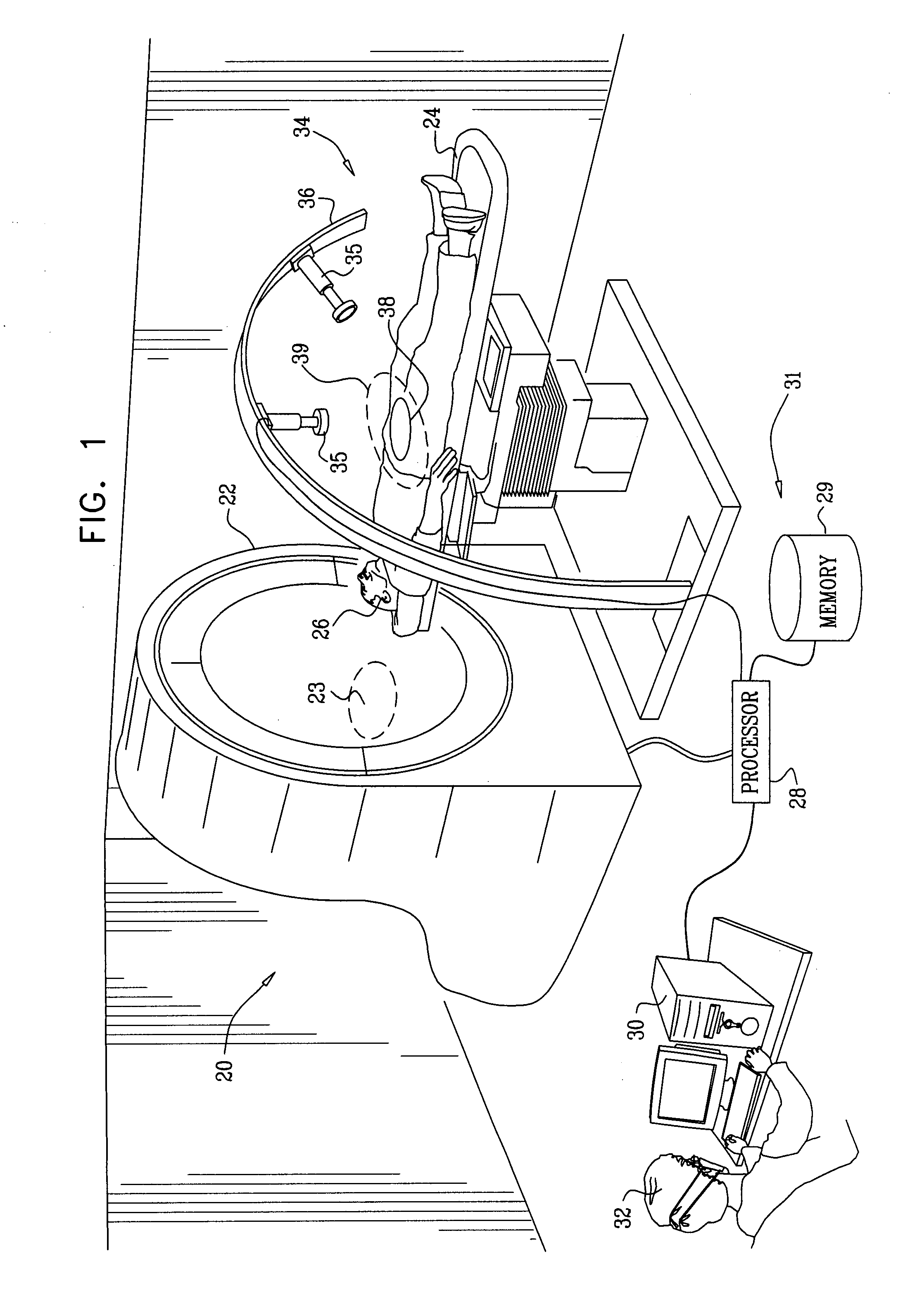
[0051]Reference is now made to FIG. 1, which is a schematic diagram of an imaging facility 20, according to an embodiment of the present invention. Facility 20 uses two systems for imaging a patient 26: a single photon emission computerized tomography (SPECT) imaging system 34, herein also termed primary imaging system 34, and a secondary imaging system 22. Secondary imaging system 22 may be used to locate a region of interest (ROI) 38 of a patient 26 that is to be imaged by the primary imaging system.

[0052]Secondary imaging system 22 typically comprises a computerized tomography (CT) machine such as an X-ray CT machine. However, embodiments of the present invention may use CT machines other than X-ray CT machines, such as CT machines that use magnetic resonance imaging (MRI). Furthermore, embodiments of the present invention may use other types of secondary imaging system, such as an ultrasonic array, for locating ROI 38. In some embodiments of the present invention, described in m...


PUM


Abstract

A method for imaging a body, including scanning the body so as to generate a tomographic image thereof, and analyzing the tomographic image to determine a location of a region of interest (ROI) within the body. The method includes providing single photon counting detector modules, each of the modules being configured to receive photons from a respective direction and to generate a signal in response thereto. The method further includes coupling each of the modules to a respective adjustable mount, adjusting each of the adjustable mounts so that the direction of the module coupled thereto is aligned with respect to the location so as to receive radiation from the ROI, operating each of the modules to receive the photons from the ROI, and, in response to the signal generated by each of the modules, generating a single photon counting image of the ROI.

Description

CROSS-REFERENCE TO RELATED APPLICATION[0001]This application is related to the U.S. Patent Application titled “Variable Collimation in Radiation Detection,” filed 28 Mar., 2007, which is assigned to the assignee of the present invention and which is incorporated herein by reference.FIELD OF THE INVENTION[0002]The present invention relates generally to imaging, and specifically to medical imaging using multiple types of radiation and multiple imaging methods and systems.BACKGROUND OF THE INVENTION[0003]A number of methods are known for non-invasively imaging internal organs, or characteristics of organs, of a patient. Such methods include X-ray and magnetic resonance imaging which use emitted radiation which behaves, and may typically be treated, largely according to its wave properties. The methods also include analyzing of radiation caused by a radioisotope that is injected into the patient. The radiation emitted in these cases may be direct or indirect emission of -rays. Direct em...

Claims


Application Information

Patent Timeline
Patent Type & Authority Applications(United States)
IPC IPC(8): G01J1/42
CPCA61B6/032A61B6/4014A61B6/463A61B6/469G01T1/1611A61B6/037
Inventor SHAHAR, ARIEEL-HANANY, URIGUTMAN, ZEEV
Owner ORBOTECH LTD
Why Eureka
Try Eureka