Vibration motor holding structure and vibration motor

a technology for vibration motors and holding structures, which is applied in the direction of electrical equipment, dynamo-electric machines, supports/encloses/casings, etc., can solve the problems of affecting the circuitry operation or motor rotation, requiring a high-cost spot welding apparatus, and unable to ensure the safety of the vibration motors, etc., to prevent the circuitry operation or function of the portable communication device from being disabled, easy to form, and low manufacturing cost

Inactive Publication Date: 2008-11-13
MINEBEA MOTOR MFG
View PDF10 Cites 11 Cited by
  • Summary
  • Abstract
  • Description
  • Claims
  • Application Information

AI Technical Summary

Benefits of technology

[0021]In the present invention, a vibration motor having an eccentric weight at an end of the rotation shaft is clamped around the outer periphery from the outside and further supported at the lower part, securely holding the entire vibration motor. Therefore, the vibration motor is not inconveniently removed from the circuit board while the motor generates vibration or when the portable communication device is accidentally dropped, preventing the circuitry operation or function of the portable communication device from being disabled.
[0022]A vibration motor body is secured and held on the holder by a simple and inexpensive means such as caulking and bonding without expensive equipment or means such as spot welding.
[0023]A holder for holding the vibration motor body on a circuit board can easily be formed by pressing and folding a sheet of steel plate, realizing low manufacturing cost.
[0024]Furthermore, in the present invention, the vibration motor is mounted on a circuit board in a tilted manner in the axial direction to increase the magnitude of vibration in the vibration motor shaft direction. A high level of body sensory vibration can be obtained using a vibration motor of the same standard under the same condition. Consequently, a vibration motor generating a necessary level of body sensory vibration can be downsized, which is advantageous in providing portable communication devices and reducing machine size, weight, and thickness.

Problems solved by technology

The above mounting methods do not ensure that the vibration motor is held by the mounting frame securely enough for the motor vibration generated by the rotation of the eccentric weight or for accidental drop of the device.
However, spot welding requires an expensive spot welding apparatus and produces spot residue or flash, which has to be removed.
When the residue or flash remains, it may adversely affect the circuitry operation or motor rotation.
Particularly, if the motor case is deformed by spot welding, it may cause a problem with the motor rotation.
However, their downsizing has a limitation since they have to generate the necessary vibration.

Method used


Image

  • Vibration motor holding structure and vibration motor
  • Vibration motor holding structure and vibration motor
  • Vibration motor holding structure and vibration motor

Examples


Embodiment Construction

[0038]The present invention will now be described hereafter with reference to the drawings.

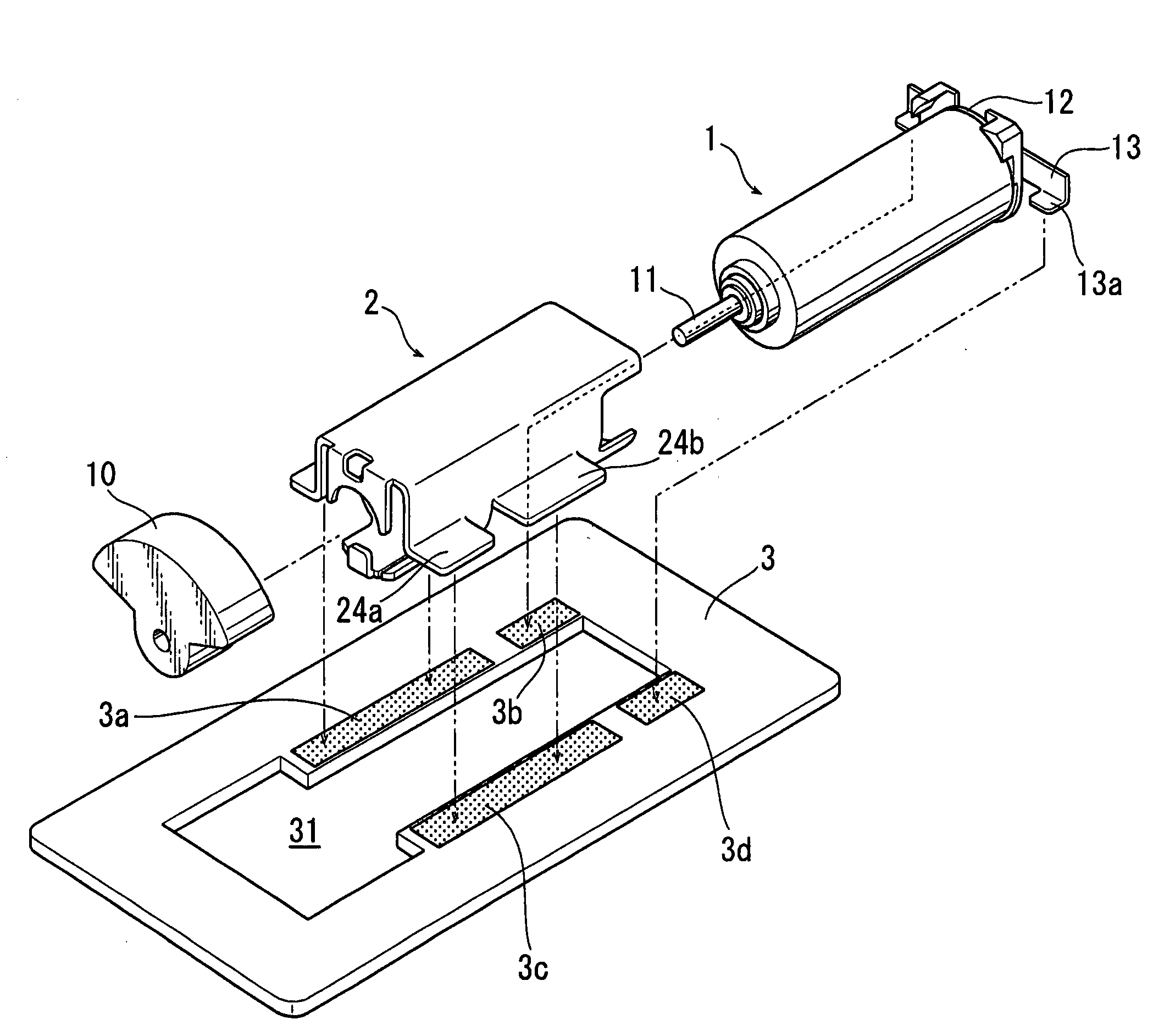
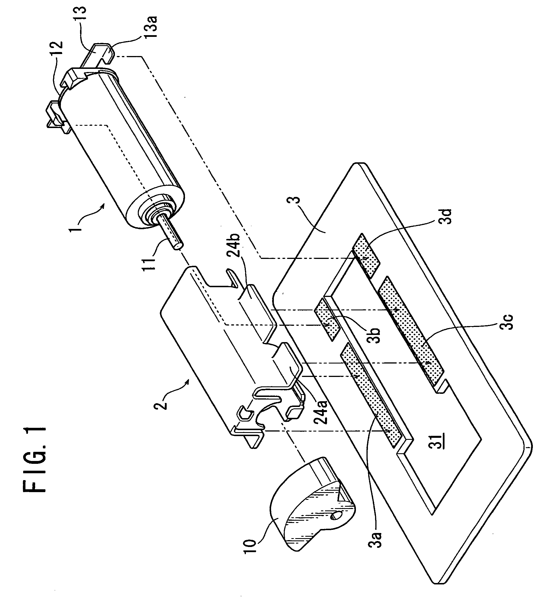
[0039]FIG. 1 is an exploded perspective view of a structure to hold on a circuit board a vibration motor used for generating vibration in a portable communication device.

[0040]FIG. 1 shows a vibration motor body 1 covered with a cylindrical motor frame, an eccentric weight 10 to be fixed to a rotation shaft 11 of the vibration motor body 1 for generating vibration, and a holder 2 designed to clamp the vibration motor body 1 around its outer periphery. Entirely clamped by the holder 2 from the outside with the eccentric weight 10 fixed thereto, the vibration motor body 1 is inserted in a cutout 31 of a circuit board 3. A resin bracket 12 is attached to the vibration motor body 1 at its rear end (the top right in the figure). A conductive external terminal 13 is fixed to the bracket 12. Brush fixed terminals of the vibration motor body 1 are electrically connected to the external terminal 13.

[00...


PUM

PropertyMeasurementUnit
thicknessaaaaaaaaaa
weightaaaaaaaaaa
tilting angleaaaaaaaaaa

Abstract

There is provided a holding structure to hold a vibration motor on a circuit board with a sufficient holding strength using an inexpensive and simple means such as caulking and bonding and a vibration motor held on a circuit board using the holding structure. The holding structure having a holder clamps a vibration motor body having an eccentric weight at an end of the rotation shaft around the outer periphery from the outside and supports the vibration motor at the lower part.

Description

CROSS-REFERENCE TO RELATED APPLICATIONS[0001]This application claims priority to Japanese Patent Application No. 2007-124572, filed May 9, 2007, and Japanese Patent Application No. 2007-137988, filed May 24, 2007, both of which are expressly incorporated herein by reference and made a part hereof.FEDERALLY SPONSORED RESEARCH OR DEVELOPMENT[0002]Not Applicable.TECHNICAL FIELD[0003]The present invention relates to a holding structure for vibration motors installed in portable communication devices such as mobile phones and PHSs and game machines to generate body sensory vibration and a vibration motor provided with the holding structure.BACKGROUND OF THE INVENTION[0004]Portable communication devices inform the wearer of an incoming call by ring tones or body sensory vibration generated by the rotation of an eccentric weight of a built-in vibration motor. The modes are switched as necessary. Some of game machines let the operator sense vibration generated by the vibration motor in the ...

Claims


Application Information

Patent Timeline
Patent Type & Authority Applications(United States)
IPC IPC(8): H02K5/00H02K7/06B21D28/02
CPCH02K5/26Y10T29/49995H02K2211/03H02K7/061Y10T83/0586
Inventor UMEHARA, MIKIOSATO, KAZUAKIKADOWAKI, DAICHI
Owner MINEBEA MOTOR MFG
Why Eureka
Try Eureka