Test circuit for performing multiple test modes

a test circuit and test mode technology, applied in the direction of testing circuits, resistance/reactance/impedence, instruments, etc., can solve the problem of restricting the ability to achieve wide-ranging failure analysis

Inactive Publication Date: 2008-11-13
SK HYNIX INC
View PDF15 Cites 15 Cited by
  • Summary
  • Abstract
  • Description
  • Claims
  • Application Information

AI Technical Summary

Benefits of technology

[0008]According to another aspect of the present invention, there is provided a test circuit comprising a first reset pulse generator configured to generate a first reset pulse when a test mode selection signal or a power-up signal is activated, and to have an active state maintained during an activation interval having a pulse width, a test mode maintenance signal generator for maintaining the activation state when a test information data is received as a predetermined test mode entry data and then generating a test mode maintenance signal reset by the first reset pulse, the test mode maintenance signal being in a reset state during the activation interval of the first reset pulse, a second reset pulse generator configured to generate a second reset pulse in response to the test information data when a reset detection signal or the power-up signal is activated, and a test mode selection signal generator configured to receive the test information data provided from the test mode maintenance signal generator during an interval at which the test mode maintenance signal is activated and to generate a specific test mode selection signal, the activated test mode selection signal being reset to be in a non-activation state by the second reset pulse.

Problems solved by technology

However, the ability to achieve wide ranging failure analysis is restricted after the semiconductor memory apparatus is packaged, which is when conventional test processes are typically run.

Method used


Image

  • Test circuit for performing multiple test modes
  • Test circuit for performing multiple test modes
  • Test circuit for performing multiple test modes

Examples


Embodiment Construction

.”

BRIEF DESCRIPTION OF THE DRAWINGS

[0010]The above and other aspects, features and other advantages of the subject matter of the present disclosure will be more clearly understood from the following detailed description taken in conjunction with the accompanying drawings, in which:

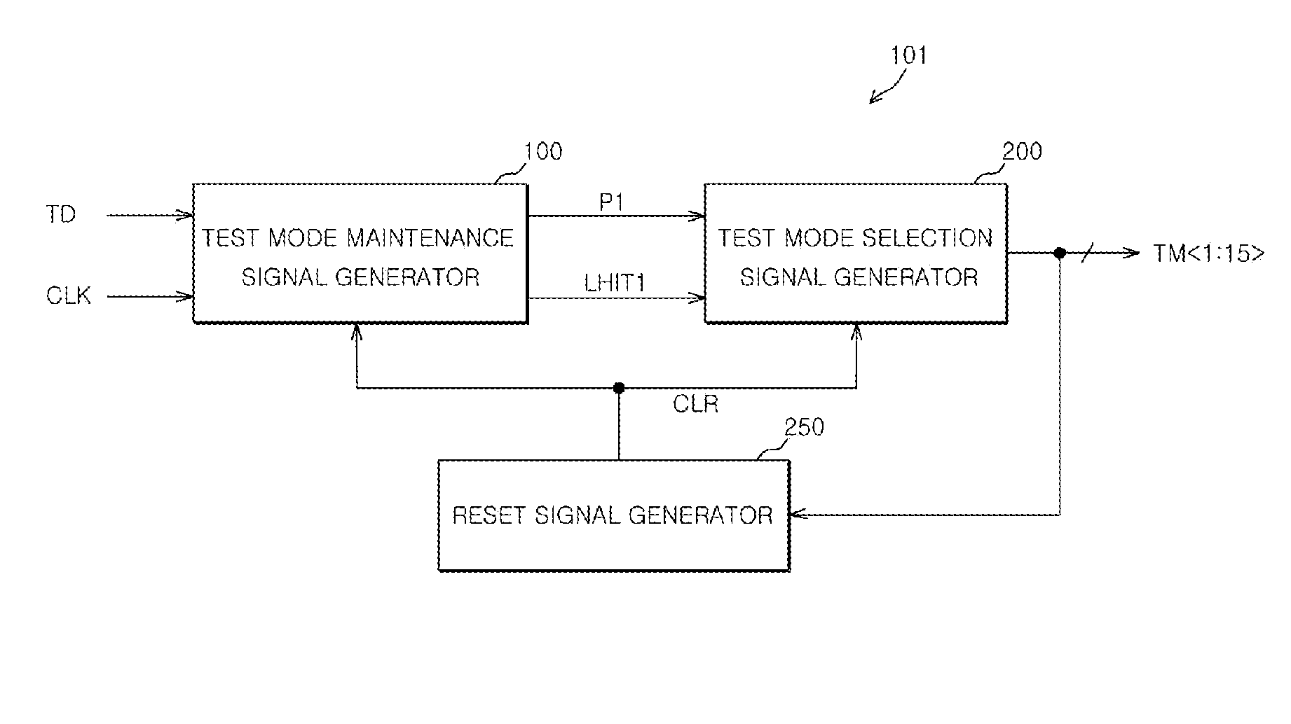
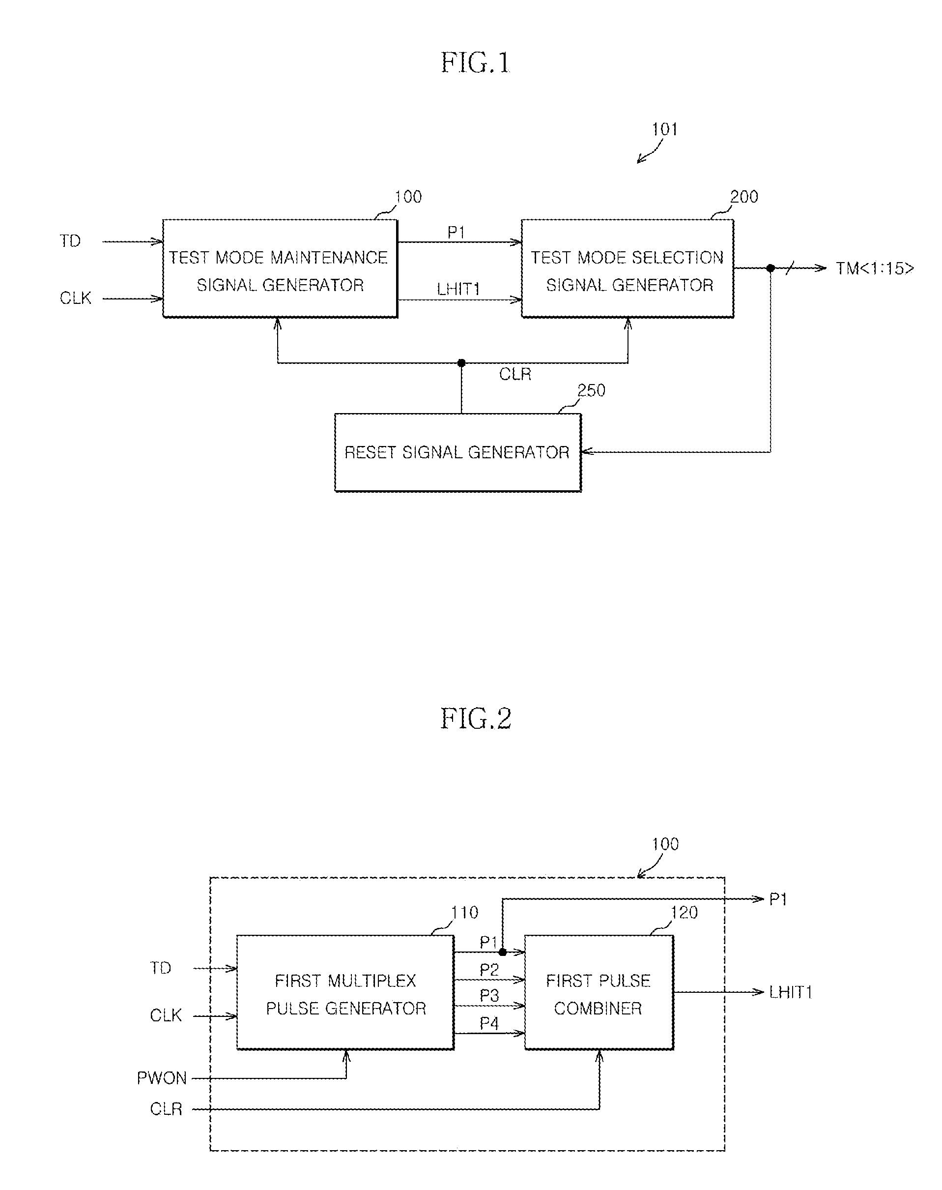
[0011]FIG. 1 is a block diagram of a test circuit according to one embodiment;

[0012]FIG. 2 is a block diagram of a test mode maintenance signal generator that can be included in the circuit illustrated in FIG. 1;

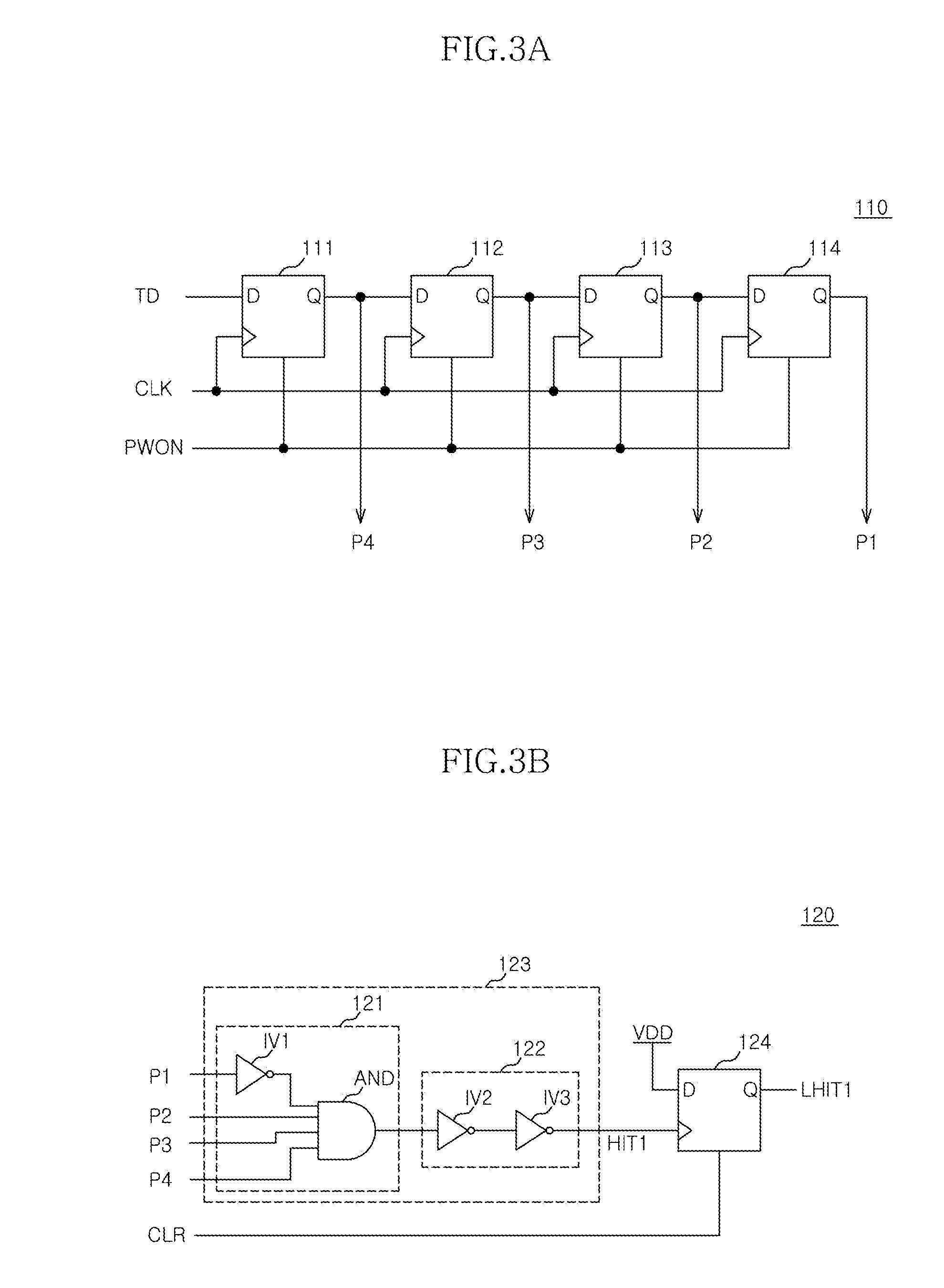
[0013]FIG. 3A is a circuit diagram of a first multiplex pulse generator in FIG. 2;

[0014]FIG. 3B is a circuit diagram of a first pulse combiner that can be included in the generator illustrated in FIG. 2;

[0015]FIG. 4A is a block diagram of a reset signal generator that can be included in the circuit illustrated in FIG. 1;

[0016]FIG. 4B is a circuit diagram of a test mode signal combiner that can be included in the generator illustrated in FIG. 4A;

[0017]FIG. 5 is a block diagram of a test mode selecti...


PUM


Abstract

A test circuit includes a first reset pulse generator configured to generate a first reset pulse when a test mode is performed or when power is up, a test mode maintenance signal generator configured to provide a test mode maintenance signal activated in response to a predetermined consecutive test information data, the activation of the test mode maintenance signal being controlled by the first reset pulse, a second reset pulse generator configured to generate a second reset pulse when the test information data is received as a predetermined test mode reset data or when power is up, and a test mode selection signal generator configured to receive the test information data provided from the test mode maintenance signal generator and the test mode maintenance signal and to generate a specific test mode selection signal, the activation of the specific test mode selection signal being controlled by the second reset pulse.

Description

CROSS-REFERENCES TO RELATED APPLICATION[0001]The present application claims priority under 35 U.S.C. 119(a) to Korean Patent Application number 10-2007-0045407, filed on May 10, 2007, in the Korean Intellectual Property Office, the contents of which are incorporated herein by reference in their entirety as if set forth in full.BACKGROUND[0002]1. Technical Field[0003]The disclosure relates to a test circuit for a semiconductor memory apparatus and, more particularly, to a test circuit for performing various test mode during testing of a semiconductor apparatus.[0004]2. Related Art[0005]Generally, after a semiconductor memory apparatus has been fabricated, a failure analysis is performed through a test process for ensuring the reliability of the semiconductor memory. That is, it must be verified whether or not the function and performance of the semiconductor memory satisfy design specifications. An error in a design and / or a failure in a process or the like is detected using the test...

Claims


Application Information

Patent Timeline
Patent Type & Authority Applications(United States)
IPC IPC(8): G01R31/02
CPCG01R31/31701G11C29/46G11C7/20G11C7/22G11C29/00
Inventor HUR, YOUNG DO
Owner SK HYNIX INC
Why Eureka
Try Eureka