
System and method for power line carrier communication using high frequency tone bursts

a power line carrier and high frequency technology, applied in the direction of ignition automatic control, electric controllers, instruments, etc., can solve the problems of affecting the efficiency of the plc system using the gated switch configuration, the inability to turn off the gate signal of the prior art system, damage the switch and/or disable the power line, etc., to achieve the effect of reducing the cost and the size of the plc communication system

Inactive Publication Date: 2008-11-13
UNIVERSAL LIGHTING TECHNOLOGIES
View PDF46 Cites 13 Cited by
  • Summary
  • Abstract
  • Description
  • Claims
  • Application Information

AI Technical Summary

Benefits of technology

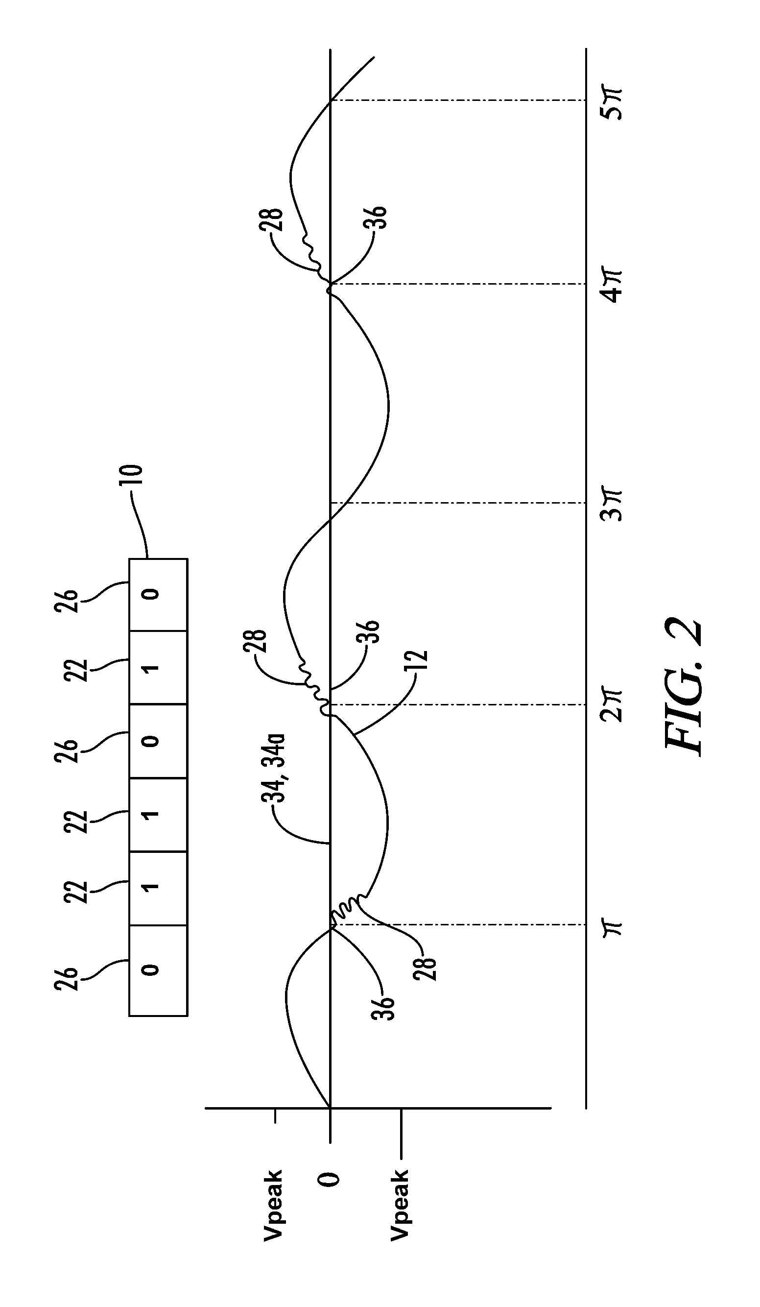
[0007]To reduce the costs and the size of a PLC communication system over an AC power line, the system and method of the present invention superimposes a tone burst into the AC power signal rather than a notch. A tone generator circuit, for example an oscillator, is connected to the AC power line to introduce this tone burst into the power signal. The presence of a tone burst on the AC power signal can indicate that a first bit value is being transmitted, such as a one. The absence of a tone burst on the AC power signal can indicate a second bit value is being transmitted, such as a zero.
[0011]Accordingly, one of the objects of the present invention is to reduce the size and cost of the components in a PLC communication system utilizing an AC power line to communicate information.
[0013]Yet another object of the present invention is to communicate information over an AC power line without creating a short circuit condition on the AC power line.
[0014]Still another object of the present invention is to create a system that is less likely to interfere with existing power line carrier systems.

Problems solved by technology

Also, many of the gated switches used in these prior art systems cannot be turned off by their gate signal.
This may damage the switch and / or disable the power line by tripping an over-current device attached to the circuit.
Also, conventional PLC systems using a gated switch configuration are less efficient and must use larger and more expensive components to handle the switching losses inherent with such systems.

Method used


Image

  • System and method for power line carrier communication using high frequency tone bursts
  • System and method for power line carrier communication using high frequency tone bursts
  • System and method for power line carrier communication using high frequency tone bursts

Examples


Embodiment Construction

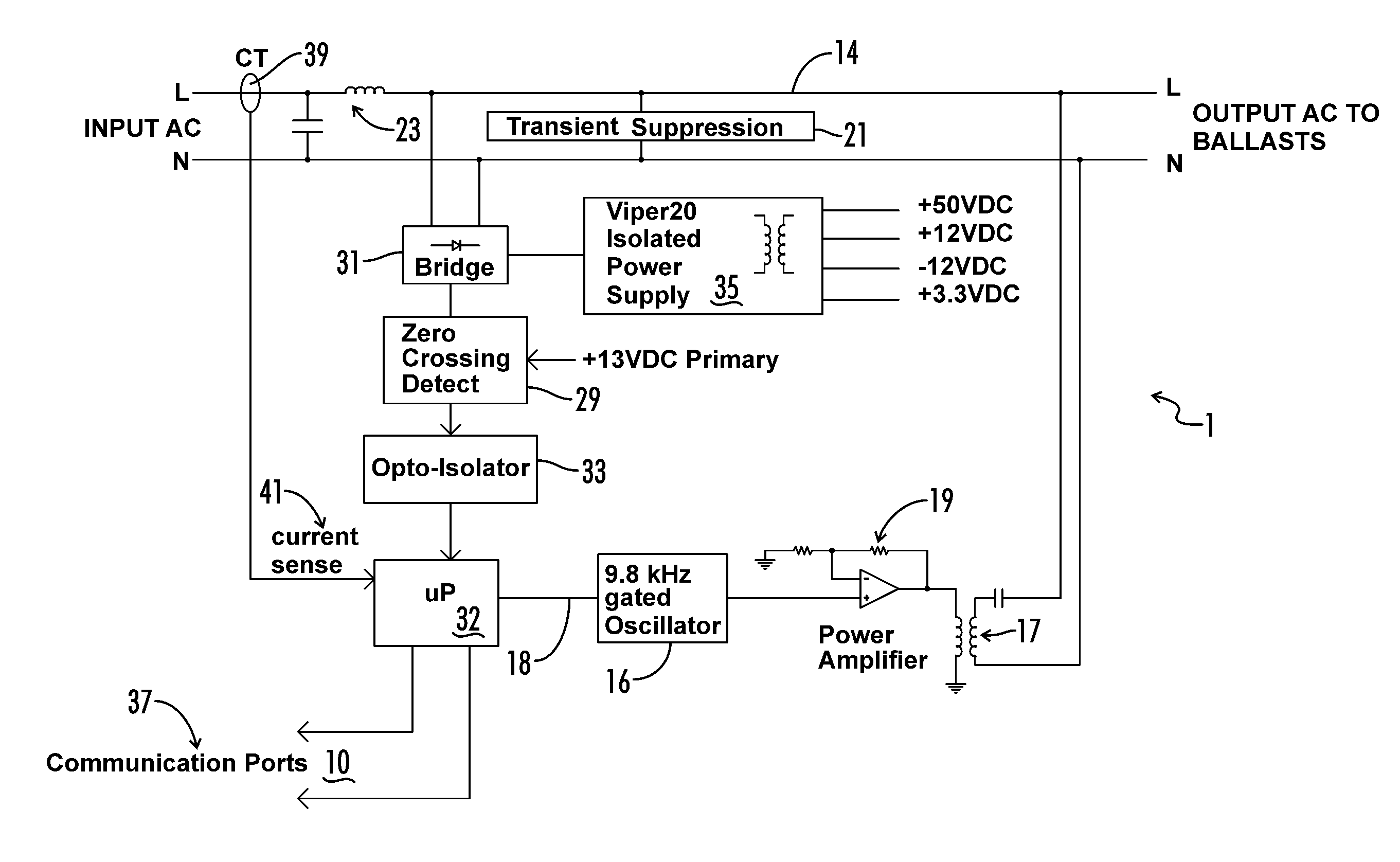
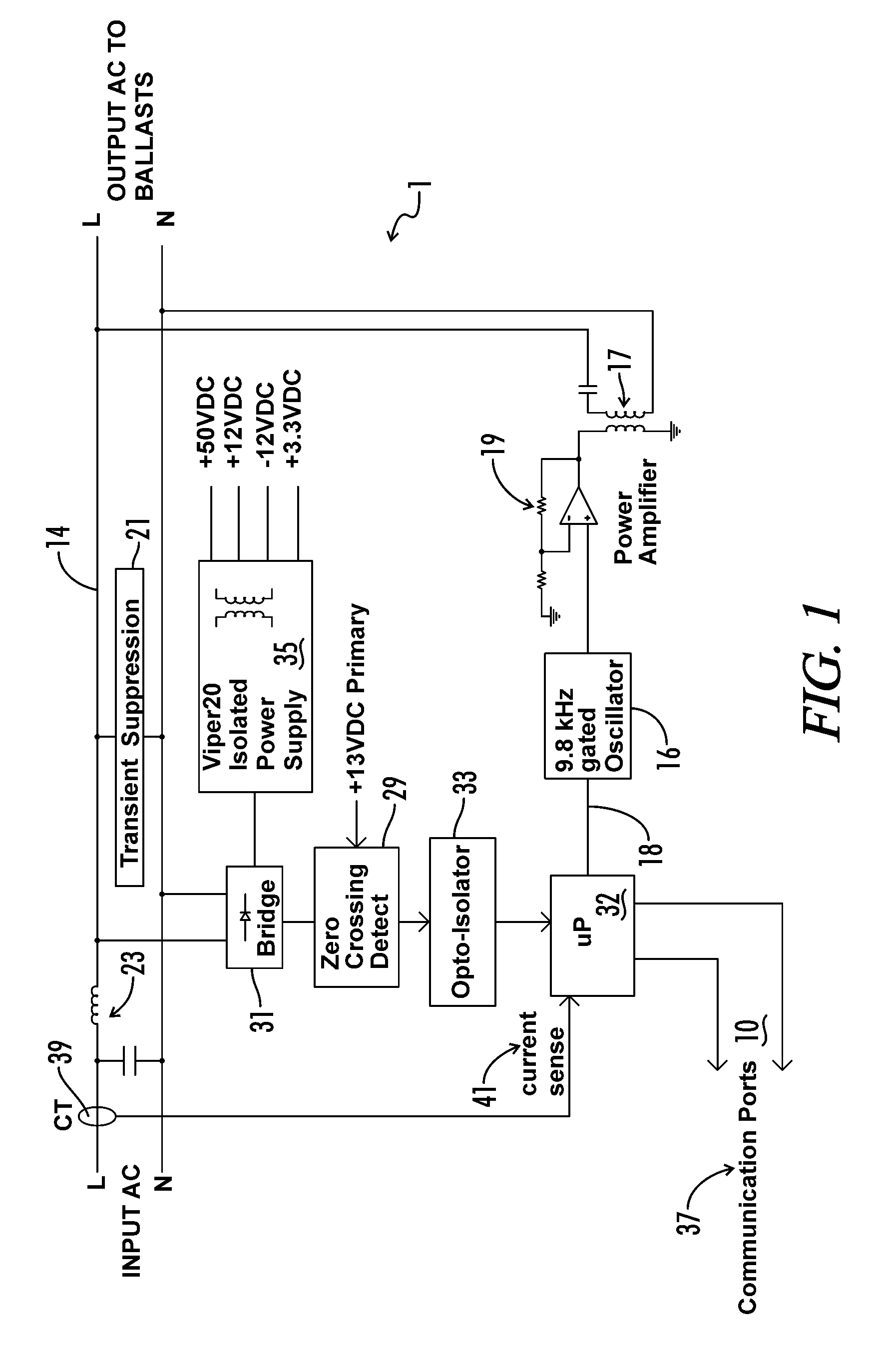
[0023]Referring now to FIGS. 1 and 2, a Power Line Carrier (PLC) communication system 1 that communicates data 10 on an AC power signal 12 transmitted along an AC power line 14 is shown. In order to communicate data 10 over the AC power line 14, the communication system 1 periodically injects high frequency tone bursts 28 on the AC power signal 12. As shown in FIG. 2, these tone bursts 28 are injected at predetermined phase angle locations along the periodic cycle of the AC power signal 12. As will be explained in more detail below, the presence or absence of these tone bursts 28 at these predetermined locations along the periodic cycle of the AC power signal 12 are utilized to determine the data bit values being transmitted along the AC power line 14. There may be a single predetermined location along the periodic cycle of the AC power signal 12 that is relevant to data transmission and detection or there may be several. In a preferred embodiment, there are two relevant predetermin...


PUM


Abstract

A communication system and method is utilized to communicate data over an AC power line. Tone burst are superimposed on an AC power signal at predetermined voltage reference levels or at predetermined phase angles to represent bit values. These bit values are represented by either the presence or the absence of the tone burst on the AC power signal. In this manner, control information can be communicated to an apparatus, such as a ballast for a gas discharge lamp.

Description

CROSS-REFERENCES TO RELATED APPLICATIONS[0001]This application is a continuation-in-part application which claims benefit of co-pending U.S. patent application Ser. No. 11 / 332,853 filed Jan. 13, 2006, entitled “Zero Crossing Detection of Line Voltage / Current of Variable Amplitude” which is hereby incorporated by reference.STATEMENT REGARDING FEDERALLY SPONSORED RESEARCH OR DEVELOPMENT[0002]Not ApplicableREFERENCE TO SEQUENCE LISTING OR COMPUTER PROGRAM LISTING APPENDIX[0003]Not ApplicableBACKGROUND OF THE INVENTION[0004]The present invention relates generally to systems and methods for communicating data across a power distribution network. More particularly, this invention relates to a system and method for communicating data using an AC power signal to a device connected to the power line for energy management and / or control of the device.[0005]Power line carrier (PLC) communication systems are frequently used to send data and control signals between devices connected to a power d...

Claims


Application Information

Patent Timeline
IPC IPC(8): G05B11/01
CPCH02J13/0027H05B37/0263Y02B70/3283Y04S20/246H02J13/00009H05B47/185Y02B90/20Y04S40/121Y02B70/30
Inventor MCKENZIE, PHILIPKOEHLER, JAMES
Owner UNIVERSAL LIGHTING TECHNOLOGIES
Learn More