
System for control of lights and motors

a technology for controlling systems and motors, applied in the field of systems for controlling lights and motors, can solve problems such as difficult to isolate communication signals from other devices connected to the power system, limitations of existing power-line carrier systems, and inability to use x10 protocol

Active Publication Date: 2008-11-13
LUTRON TECH CO LLC
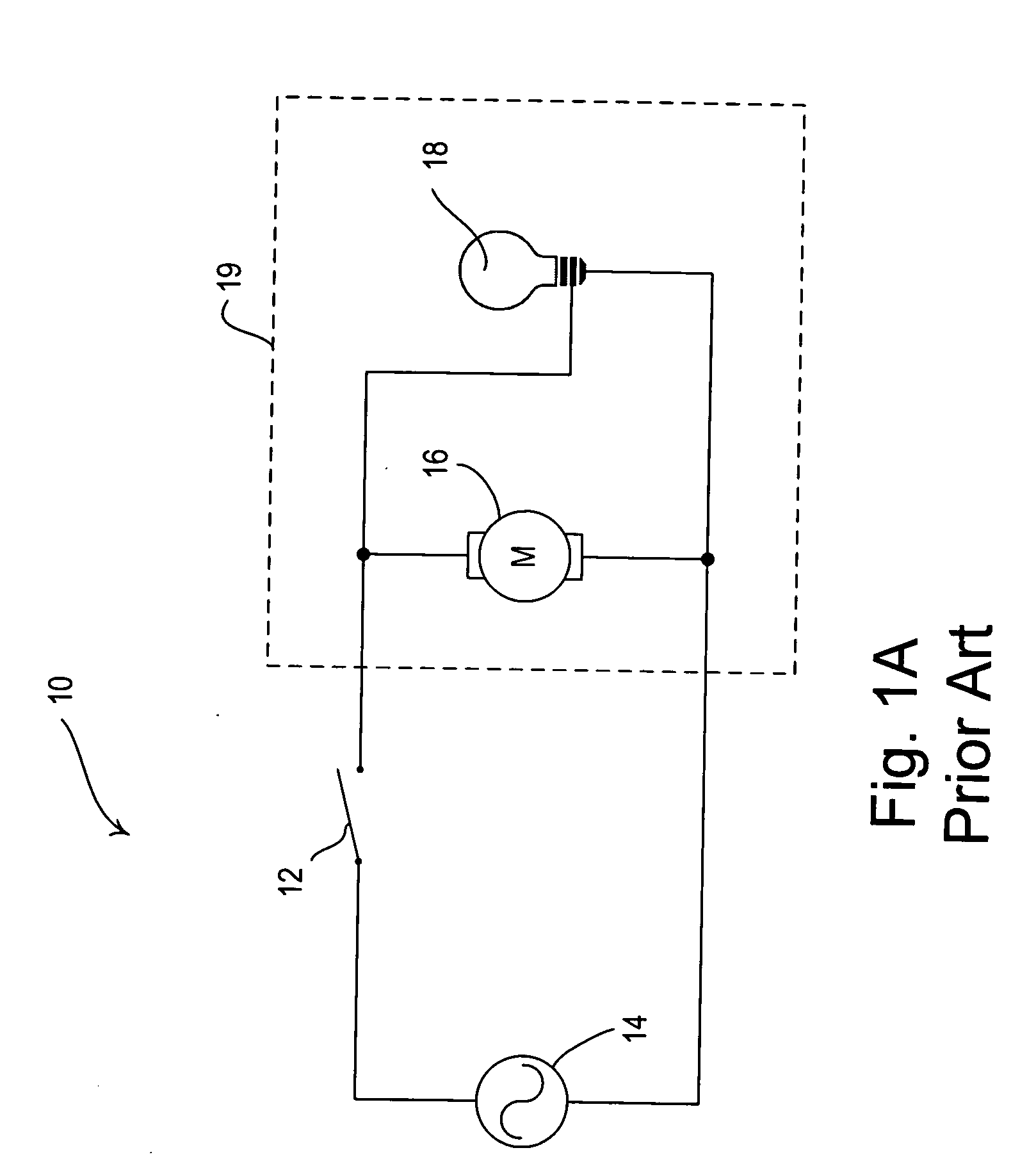
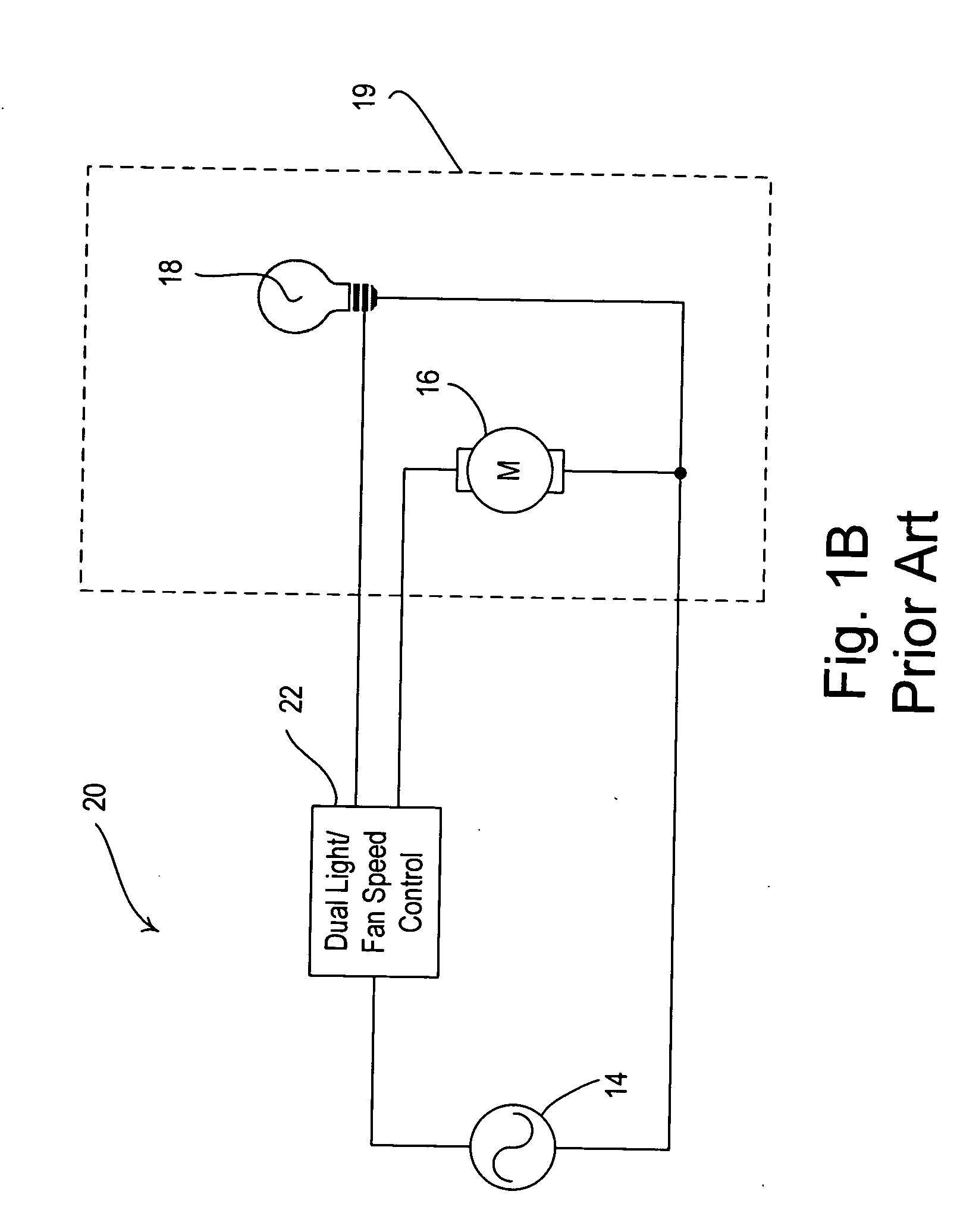
View PDF36 Cites 63 Cited by
  • Summary
  • Abstract
  • Description
  • Claims
  • Application Information

AI Technical Summary

Benefits of technology

Enables reliable and independent control of fan motors and lighting loads from a remote location using existing building wiring, improving communication reliability and eliminating the need for a neutral connection, while minimizing voltage drop and ensuring safe operation.

Problems solved by technology

However, existing power-line carrier systems have some limitations.
Also, since the X10 protocol utilizes voltage carrier technology, communication messages are transmitted throughout the power system and it is difficult to isolate the communication signals from other devices connected to the power system.
Finally, the X10 protocol is not a “reliable” communication scheme since no acknowledgements are sent to a transmitting device when a receiving device has received a valid message.
However, many of these systems are unreliable, provide erratic, noisy operation, and require a neutral connection.

Method used


Image

  • System for control of lights and motors
  • System for control of lights and motors
  • System for control of lights and motors

Examples


first embodiment

[0066]Next, the median filter 200 determines the median of the W samples at step 268. According to the present invention, the median filter 200 groups (i.e., orders) the ones and zeros of the W samples and determines the value of the middle sample. For example, if the present W samples are[0067]1011001,

the median filter 220 will group the zeros and the ones to form a sorted sample stream[0068]0001111.

The median for the sorted sample stream is one, since the median or middle value is one.

second embodiment

[0069]According to the present invention, the median filter 220 counts the number of ones in the W samples to determine the median at step 268. For an Nth order median filter, the median is one if the count of the ones is greater than or equal to the value of N+1. Otherwise, the median is zero. Thus, for a 3rd order median filter, if there are four ones in the W samples, the median will be equal to one. Accordingly, the width W of the median filter 220 must always be an odd number, i.e., 2N+1. The median filter 220 is preferably implemented with a lookup table that counts the ones and returns a one if the count is greater than or equal to N+1 or a zero otherwise. By using the lookup table, the filtering process is able to complete in a few instruction cycles thereby making the computation on a microcontroller exceptionally fast.

[0070]Finally, at the step 270, the median filter 220 provides the median determined in step 268 as the output sample 272 to form the filtered Manchester enc...


PUM


Abstract

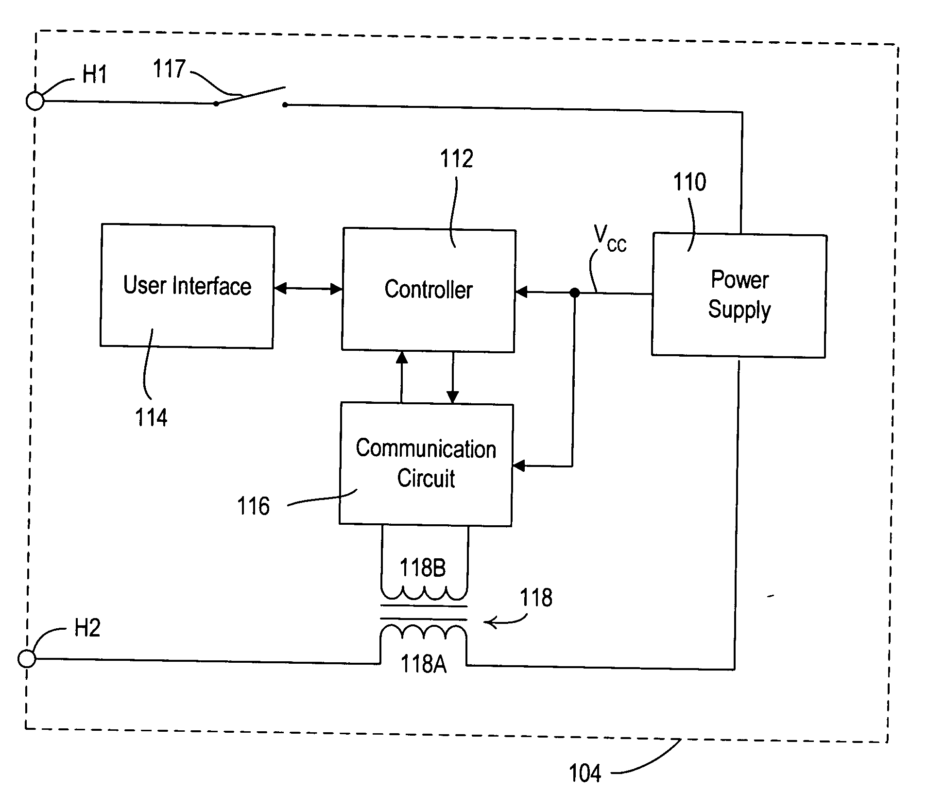
A system for independent control of electric motors and electric lights includes a plurality of two-wire wallstations coupled in series via power wires between an alternating-current (AC) source and a light / motor control unit. The light / motor control unit is preferably located in the same enclosure as an electric motor and an electric light and has two outputs for independent control of the motor and the light. The light / motor control unit and the wallstations each include a controller and a communication circuit that is coupled to the power wiring via a communication transformer and communicate with each other using a loop current carrier technique. The light / motor control unit and the wallstations utilize pseudo random orthogonal codes and a median filter in the communication process.

Description

RELATED APPLICATIONS[0001]This application claims priority from commonly-assigned U.S. Provisional Application Ser. No. 60 / 687,689, filed Jun. 6, 2005, having the same title as the present application, the entire disclosure of which is hereby incorporated by reference.BACKGROUND OF THE INVENTION[0002]1. Field of the Invention[0003]The present invention relates to an apparatus for independently controlling a motor, such as, for example, a fan motor, together with a lighting source contained within the same enclosure as the motor and coupled to the motor. The invention also relates to a communication scheme for communicating over a power line to control the load, such as, for example, a fan motor and a light.[0004]2. Description of the Related Art[0005]It is often desirable to include a lamp and a fan motor in a single enclosure. Since the lamp and the fan motor are often wired in parallel, the lamp and the fan motor are generally controlled together from a switch located remotely fro...

Claims


Application Information

Patent Timeline
Patent Type & Authority Applications(United States)
IPC IPC(8): G05B11/01H02P29/00
CPCH04B3/54H04B2203/5458H04L1/0054H04L1/0072H04L1/1812H04L25/0266H04L25/0282H04B2203/5412H04B2203/5416
Inventor STEINER, JAMES P.DOBBINS, AARONBLAIR, EDWARD J.
Owner LUTRON TECH CO LLC
Learn More