Method and Device for Determining the Vehicle Class of Vehicles

a vehicle and class technology, applied in the field of vehicle classification, can solve the problems of increasing the error, increasing the error, and not so as to achieve the effect of improving the accuracy of the discrimination criteria of vehicle length and obtaining more accurately

Inactive Publication Date: 2008-11-13
ROBOT VISUAL SYST
View PDF7 Cites 38 Cited by
  • Summary
  • Abstract
  • Description
  • Claims
  • Application Information

AI Technical Summary

Benefits of technology

[0033]It is essential to the invention that the length criteria will be improved by limiting the tolerance width for the passage distance d, in that the passage distance d is determined by means of the detection of range values E and thus the vehicle length L can be derived more accurately.

Problems solved by technology

However, because the goal is not primarily to determine the vehicle length L, but instead to use it as means to be able to classify the measured vehicle, it is sufficient to determine length criteria that allow the vehicle to be assigned unambiguously to only one vehicle class.
The accuracy of the discrimination criteria of vehicle length is therefore not improved.
In both cases, the obtained length values are equally subject to error because the passage distances for vehicles traveling at different ranges to the radar device are not constant.
The greater the horizontal beam spread angle of the radar cone, the greater the error.

Method used


Image

  • Method and Device for Determining the Vehicle Class of Vehicles
  • Method and Device for Determining the Vehicle Class of Vehicles
  • Method and Device for Determining the Vehicle Class of Vehicles

Examples


first embodiment

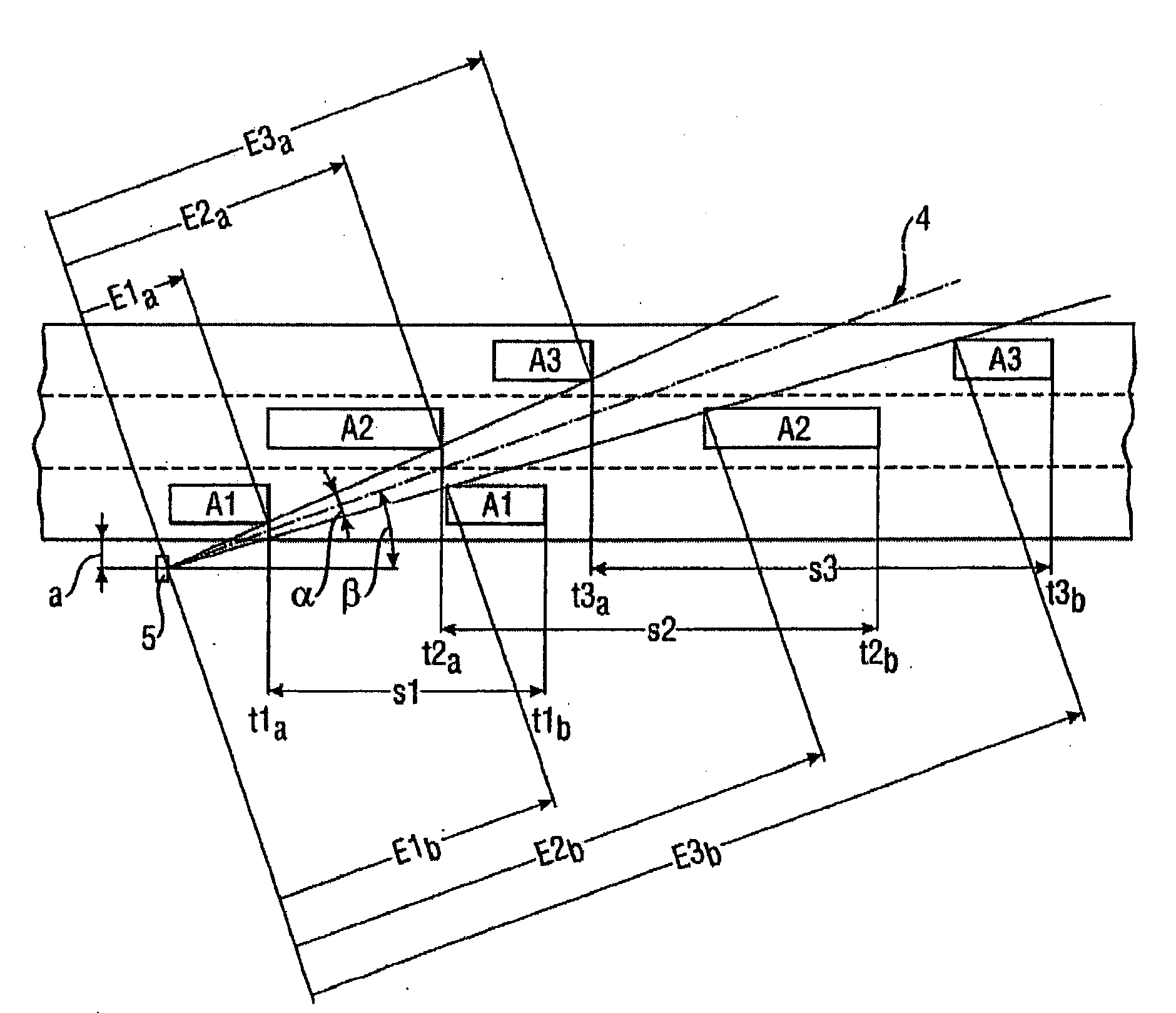
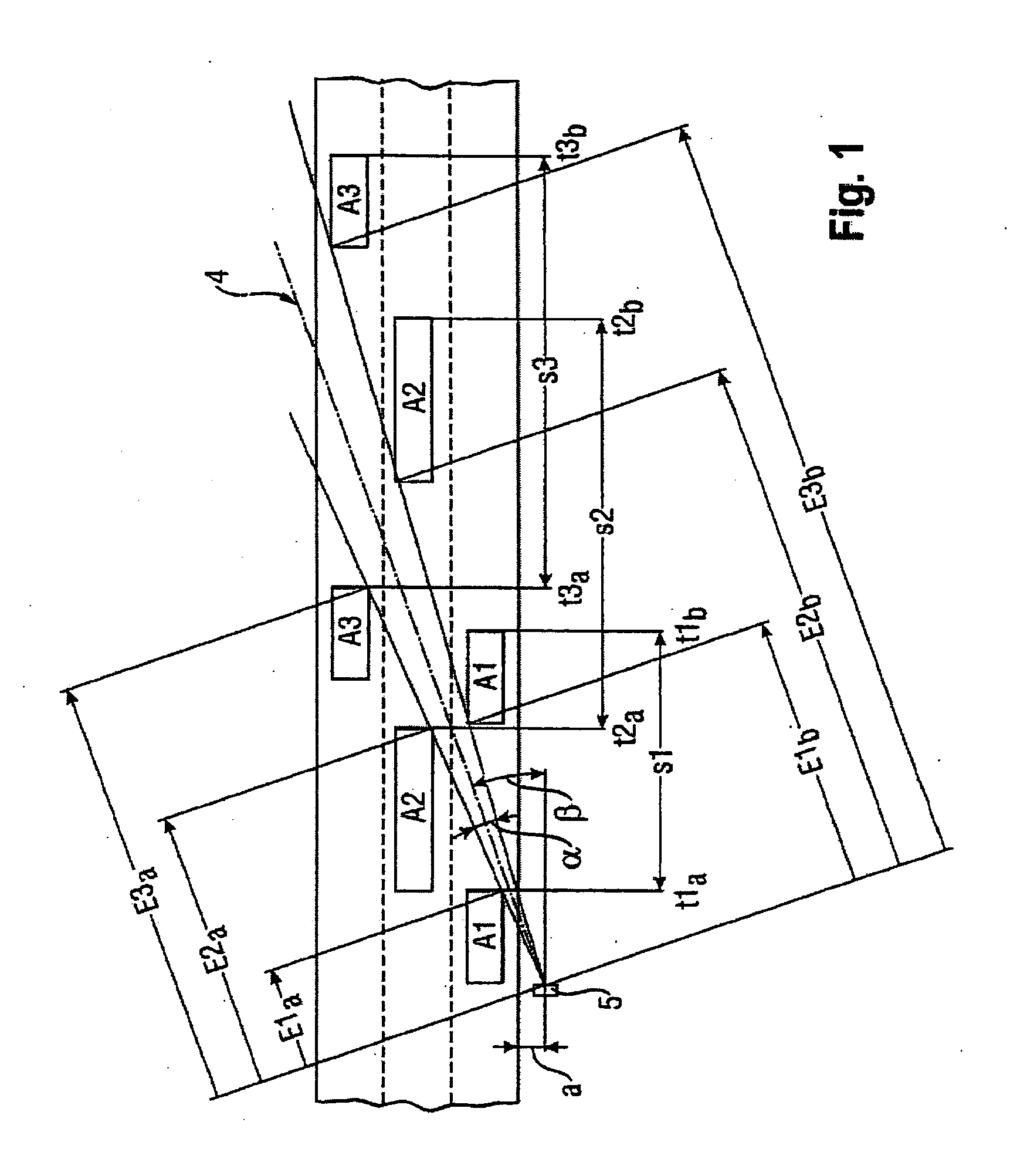
[0044]To be able to reach a conclusion on a passage distance d directly via the range E, in a first embodiment with reference to FIG. 2, a measured value detection of the range E at the time point of the entry t2a of a second vehicle A2 into the radar cone 4 and at the time point of the exit t2b of this vehicle A2 from the radar cone 4 should be measured. The passage distance d2 is here given from the formula d2=cos(β−α / 2)·E2b−cos(β+α / 2)·E2a.

[0045]By subtracting the passage distance d2 from the driven distance s2 determined in a known way, the vehicle length L2 is given.

[0046]Through a more accurate determination of the driven distance s, the tolerance range for the vehicle length L is considerably reduced. To view the driven distance s as a limited straight line, however, is an idealization, in which the vehicle A, considered as reduced to a point, exactly maintains its direction of travel, i.e., the path that the vehicle A travels describes is a straight line.

[0047]Even if the veh...

second embodiment

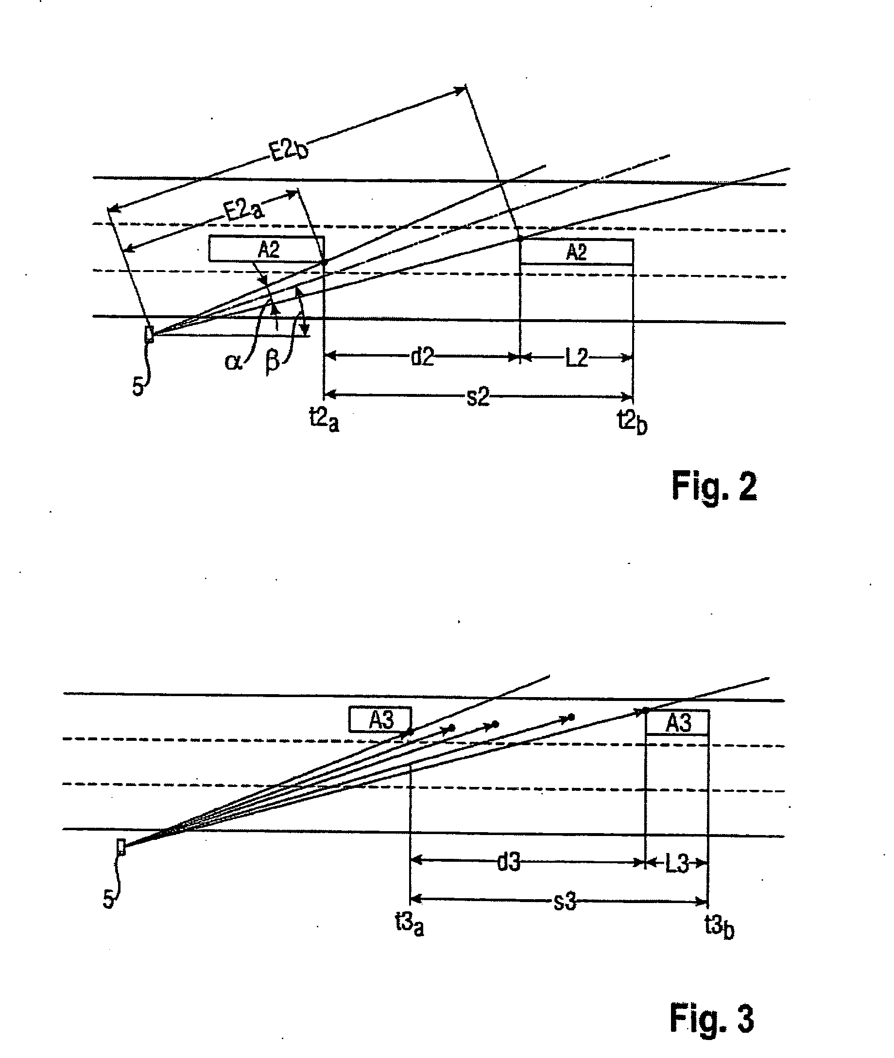
[0048] the range measurement could also be determined over the entire passage time, in order to determine from it the vehicle path described by vehicle A and thus the driven distance s, i.e., its length, with even more precision.

[0049]In FIG. 3, five measurement time points are shown. It is clear that the range values E after entry lie on a straight line parallel to the direction of travel as long as the vehicle A has not yet completely entered into the radar cone 4. Then the range value E quickly increases, which is based on the fact that the rear end reflects as a reflector in addition to the vehicle side. From this it also becomes clear that different vehicle contours deliver different signal profiles, which shall be discussed in more detail further below.

[0050]The range values E do not follow the described rule when the vehicle A does not travel constantly in the direction of travel of the roadway.

[0051]With the entry of a vehicle A into the radar cone 4 (measurement range), the...


PUM


Abstract

The invention relates to a method and device with which a vehicle traveling through a radar cone is classified by means of length criteria. The length criteria are formed by the difference of the driven distance that the vehicle covers, during which it reflects the radar beam, and the passage distance of the vehicle through the radar cone, which gives a more or less precise measurement for the vehicle length according to the accuracy of the determined passage distance. For determining the passage distance, range values are derived from the radar signals.

Description

FIELD OF THE INVENTION[0001]The invention relates to a method for classifying a vehicle as it is driven past a radar beam directed onto a roadway.BACKGROUND OF THE INVENTION[0002]Such a method is known according to the class from Patent Application No. EP 0 067 905 A1.[0003]Doppler radar systems are used in traffic measurement technology especially for monitoring and enforcing legal speed limits for vehicles. Here it can be of interest not only to detect the speed of a vehicle, but also to classify the vehicle.[0004]EP 0 067 905 A1 relates to a method and to a device in which the speed of a measured vehicle and discrimination criteria for assigning the vehicle to a vehicle class are derived by means of the evaluation of signals of a Doppler radar speed measurement device. In this way it becomes possible to trigger a camera when different maximum speeds allocated to different vehicle classes are exceeded. As discrimination criteria, criteria for the vehicle length are detected, deter...

Claims


Application Information

Patent Timeline
Patent Type & Authority Applications(United States)
IPC IPC(8): G01S13/58G01S13/08
CPCG01S7/41G01S13/92G08G1/015
Inventor BEHRENS, ANDREAS
Owner ROBOT VISUAL SYST
Why Eureka
Try Eureka