Wideband dielectric resonator antenna

Inactive Publication Date: 2008-11-13
NAT TAIWAN UNIV
View PDF14 Cites 271 Cited by
  • Summary
  • Abstract
  • Description
  • Claims
  • Application Information

AI Technical Summary

Benefits of technology

[0007]The resonator is a dielectric resonator. The dielectric resonator comprises the notch. Therefore, when electric lines pass the notch to the short-circuited element, the electric field thereof is amplified for several times and can be radiated more efficiently. Hence, the quality factors of the

Problems solved by technology

However, conventional dielectric resonator antennas require a complex manufacturing process and increase

Method used


Image

  • Wideband dielectric resonator antenna
  • Wideband dielectric resonator antenna
  • Wideband dielectric resonator antenna

Examples


Embodiment Construction

[0013]The following description is of the best-contemplated mode of carrying out the invention. This description is made for the purpose of illustrating the general principles of the invention and should not be taken in a limiting sense. The scope of the invention is best determined by reference to the appended claims.

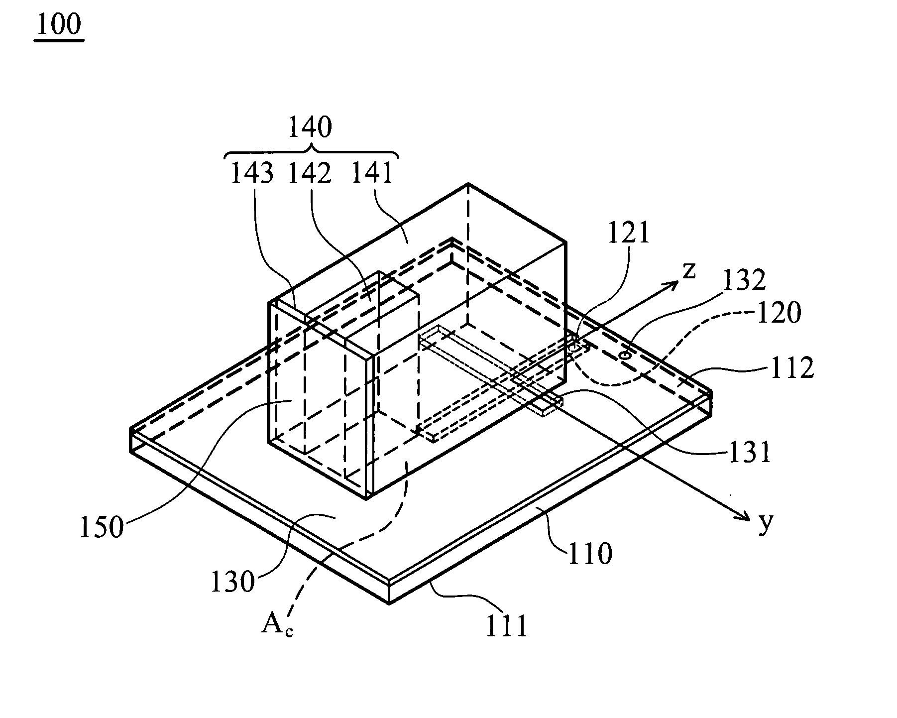
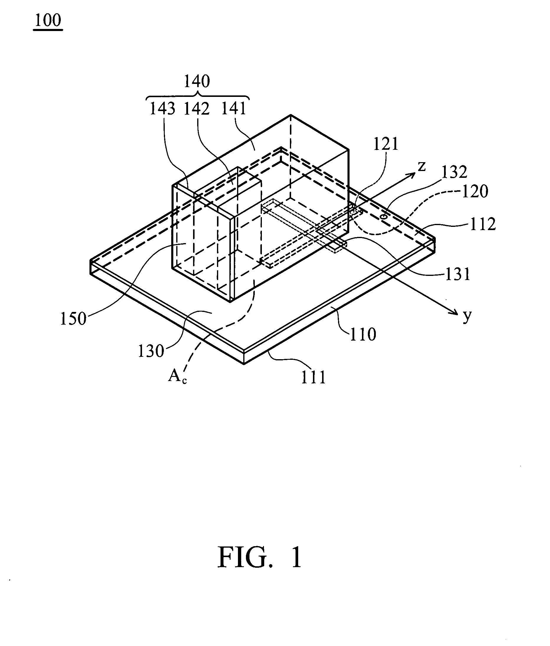
[0014]FIG. 1 shows an antenna 100 of the invention, which is a notched wideband dielectric resonator antenna, comprising a substrate 110, a feed conductor 120, a ground layer 130, a resonator 140 and a short-circuited element 150. The substrate 110 comprises a first surface 111 and a second surface 112. The feed conductor 120 is formed on the first surface 111. The ground layer 130 is formed on the second surface 112. The ground layer 130 comprises an aperture 131. The resonator 140 is disposed on the ground layer 130 comprising a body 141 and a notch 142. The notch 142 is formed on a first side 143 of the body 141. The first side 143 is perpendicular to the ground lay...


PUM


Abstract

An antenna comprises a substrate, a feed conductor, a ground layer, a resonator and a short-circuited element. The substrate comprises a first surface and a second surface. The feed conductor is formed on the first surface. The ground layer is formed on the second surface, comprising an aperture. The resonator is disposed on the ground layer, comprising a body and a notch, the notch is formed on a first side of the body, wherein the first side is perpendicular to the ground layer. The short-circuited element is disposed on the first side connecting the ground layer.

Description

BACKGROUND OF THE INVENTION[0001]1. Field of the Invention[0002]The invention relates to an antenna, and more particularly to a wideband dielectric resonator antenna.[0003]2. Description of the Related Art[0004]The sizes of conventional dielectric resonator antennas can be reduced by using grounded metal plates at the cost of bandwidth reduction. Conventionally, resonators with different shapes (for example, resonators with a triangular and circular cross section) are stacked to increase bandwidth of dielectric resonator antennas. Or, resonators which transmit signals in different bands are incorporated into one dielectric resonator antenna to provide an increased bandwidth. However, conventional dielectric resonator antennas require a complex manufacturing process and increased cost, and size thereof is large, thus preventing utilization in minimized portable electronic devices.BRIEF SUMMARY OF THE INVENTION[0005]A detailed description is given in the following embodiments with ref...

Claims


Application Information

Patent Timeline
IPC IPC(8): H01Q1/38H01Q5/10
CPCH01Q1/38H01Q9/0485
Inventor CHANG, TZE-HSUANKIANG, JEAN-FU
Owner NAT TAIWAN UNIV
Why Eureka
Try Eureka