Antenna

a technology of resonant modes and antennas, applied in the field of antennas, can solve the problems of significant differences in the impedance of the first and second resonant modes, and achieve the effect of good impedance matching

Inactive Publication Date: 2008-11-13
NOKIA CORP
View PDF8 Cites 7 Cited by
  • Summary
  • Abstract
  • Description
  • Claims
  • Application Information

AI Technical Summary

Benefits of technology

[0003]It would therefore be desirable to provide an antenna having multiple resonant modes that has good impedance matching at both the first and the second lowest resonant modes.

Problems solved by technology

A problem with this type of PIFA is that the impedance for the first and second resonant modes may be significantly different.

Method used


Image

  • Antenna
  • Antenna
  • Antenna

Examples


Embodiment Construction

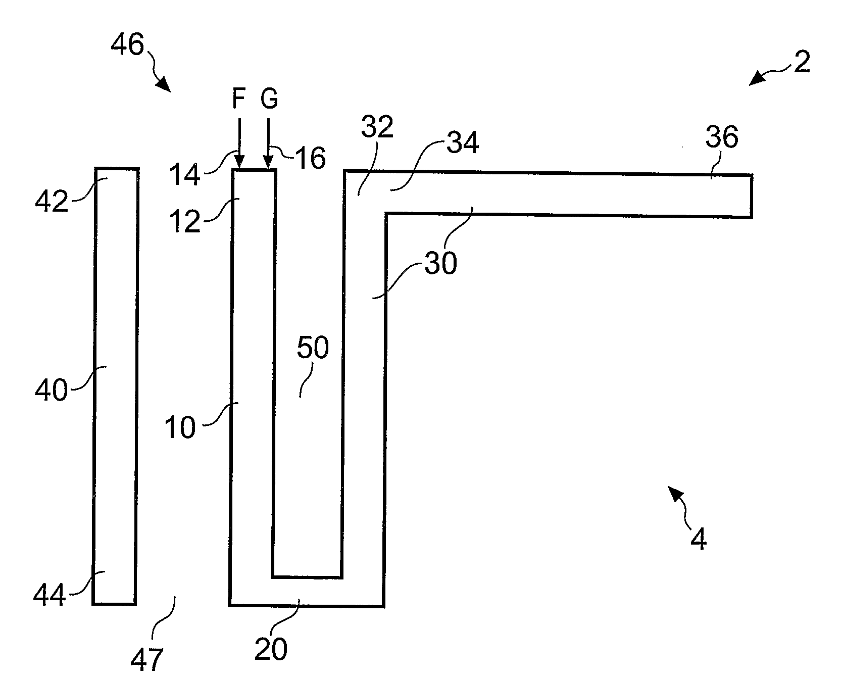
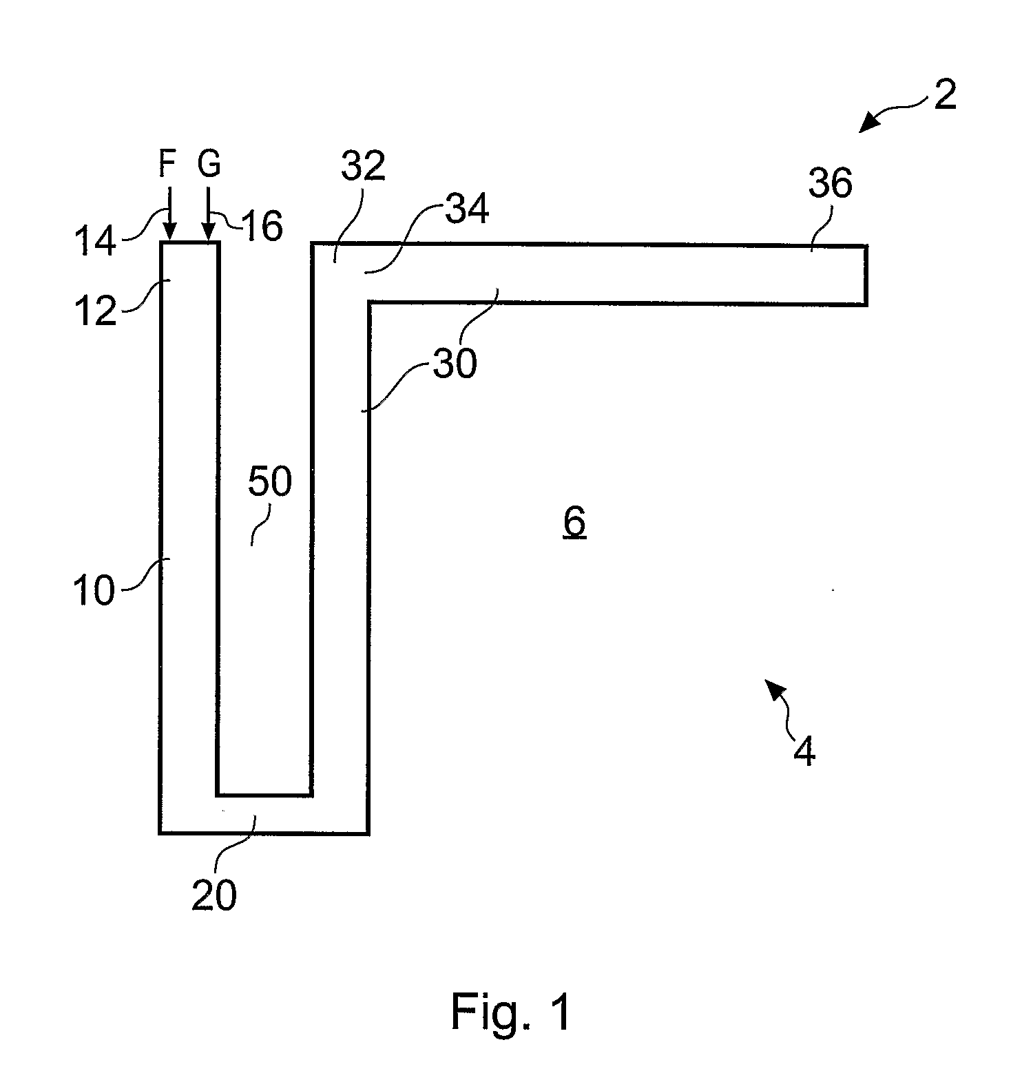
[0032]FIG. 1 schematically illustrates a planer inverted F antenna (PIFA) 2. The antenna 2 comprises an antenna element 4, and a ground plane 6. The antenna element 4 has a feed pin 14 and a ground pin 16 at a first part 12. The feed pin 14 and the ground pin 16 can be swapped. The ground pin 16 connects the antenna element 4 to the ground plane 6. The feed pin 14 provides a signal for driving the antenna 4. The antenna element 4, being a PIFA, is planar and typically lies within a plane that is parallel to the ground plane 6.

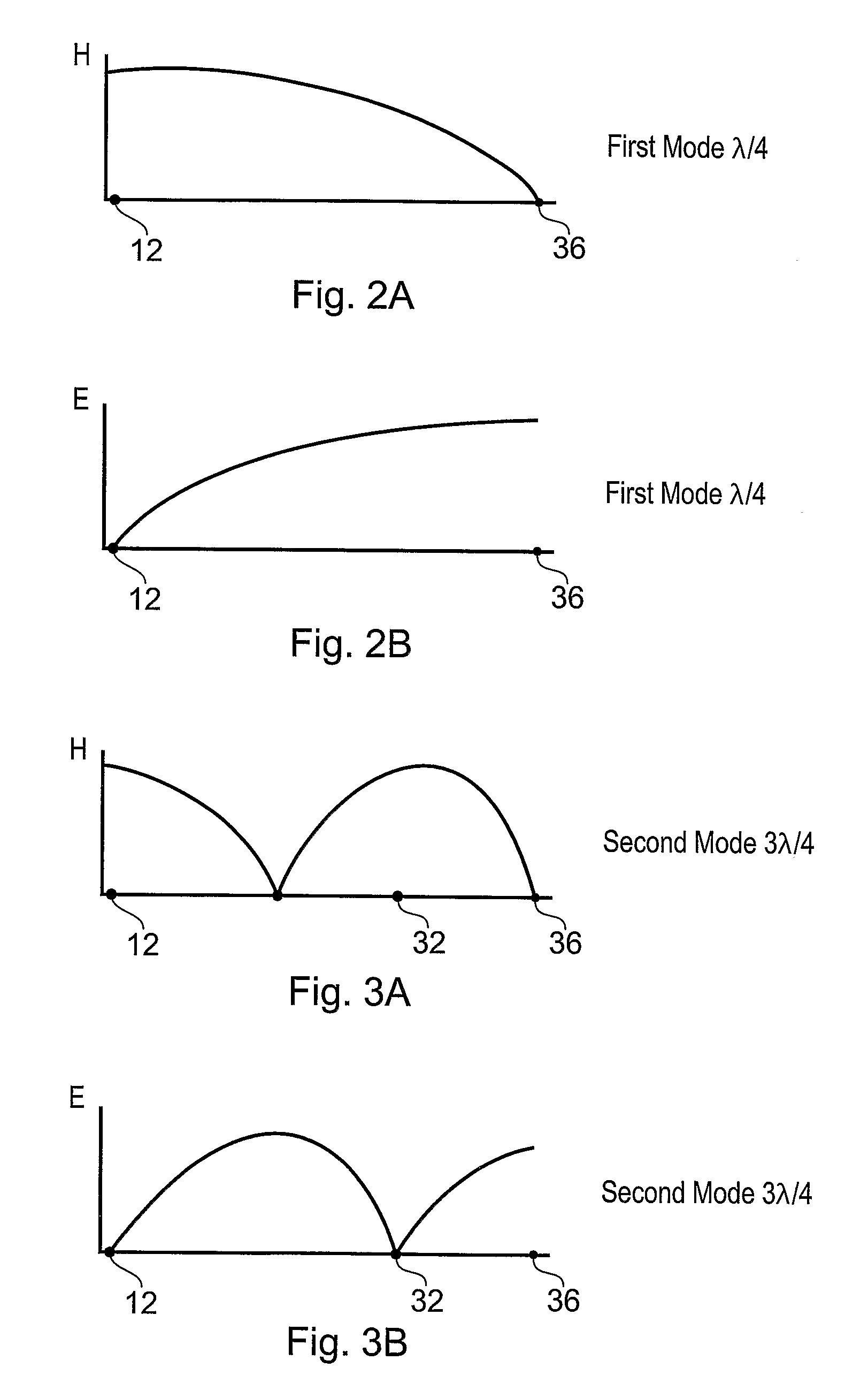
[0033]The antenna 2 has at least two resonant modes of operation. The first resonant mode is the lowest frequency resonant mode. It corresponds to a λ / 4 resonant mode of the PIFA. The second resonant mode is the second lowest frequency resonant mode of the antenna. It corresponds to the 3λ / 4 resonant mode of the PIFA. Consequently, in the first resonant mode, the antenna 2 has a resonant frequency that corresponds to a wavelength λ1, where λ1=4 L, L being the e...


PUM


Abstract

An antenna having a first resonant mode and a second resonant mode and including an antenna element, the antenna element including a first portion; a second portion; and at least one bend between the first portion and the second portion, wherein a first part of the first portion opposes a second part of the second portion across a narrow gap and, in use, a maximum of current density for the second resonant mode is at or adjacent each of the first part of the first portion and the second part of the second portion.

Description

FIELD OF THE INVENTION[0001]Embodiments of the present invention relate to an antenna. In particular they relate to antennas having multiple resonances.BACKGROUND TO THE INVENTION[0002]PIFA antennas are widely used in mobile handsets and depending upon their construction they may have multiple resonant frequencies. Such a PIFA may have a central feed and ground and a number of elements separately extending from the feed each of which has a different resonant frequency. In order to save space, a PIFA comprising only one element has been constructed. It has resonant frequencies which correspond to ¼ and ¾ wavelengths. A problem with this type of PIFA is that the impedance for the first and second resonant modes may be significantly different. Therefore although the impedance for the lowest resonant mode may be close to 50 Ohms, the impedance for the second lowest resonant mode would be significantly greater than 50 Ohms.BRIEF DESCRIPTION OF THE INVENTION[0003]It would therefore be des...

Claims


Application Information

Patent Timeline
Patent Type & Authority Applications(United States)
IPC IPC(8): H01Q9/04
CPCH01Q9/0421H01Q5/10H01Q1/38H01Q13/08
Inventor WANG, HANYANGZHENG, MING
Owner NOKIA CORP
Why Eureka
Try Eureka