Display Device

a display device and display technology, applied in the field of display devices, can solve the problems of personal information being abused, etc., and achieve the effect of preventing the upsizing and complexity of the display devi

Inactive Publication Date: 2008-11-13
TPO HONG KONG HLDG
View PDF4 Cites 12 Cited by
  • Summary
  • Abstract
  • Description
  • Claims
  • Application Information

AI Technical Summary

Benefits of technology

[0007]According to the present invention, the first data corresponding to an intensity of said light detected by said light detecting means is held in the holding means, and the refreshing means writes the second data into said holding means on the basis of said first data on purpose. Therefore, the first data held in the holding means is prevented from changing to unintended data, a correct data related to the object can be obtained. The light from the object is, for example, light emitted from the object, light reflected by the object, and so on. The light detecting means, the holding means, and the refresh means are provided in the pixel or sub pixel, so that upsizing and complexity of the display device are prevented. The first data may be the same as the second data or may be different from the second data. The first and second data can be represented in the form of voltage, current, or the amount of charge.

Problems solved by technology

Therefore, if the third party saw the personal information stored in the mobile phone or the personal computer, the personal information might be abused.
However, if the password were seen by the third party, the personal information might be abused.

Method used


Image

  • Display Device
  • Display Device
  • Display Device

Examples


first embodiment

[0053]Since the first to third refresh switches 14, 16 and 17 are in the on-state when the refresh means 18 is writing the voltage Vdd or Vss into the node N1, the node N1 can be connected to the processing circuit by turning the readout switch 19 on. However, if the pixels P(1, k), P(2, k), . . . , P(m, k) turned the readout switches 19 on simultaneously, the voltages on the nodes N1 of the pixel P(1, k), P(2, k), . . . , P(m, k) would collide with each other on the source line Sk, so that correct voltage values could not be supplied to the processing circuit. To overcome this problem, in the first embodiment, the readout switches 19 of the pixels P(1, k), P(2, k), . . . , P(m, k) are in turn set to on-state. More specifically, during the readout period (ro1) (the instant t9 to t10), the readout switch 19 of only pixel P(1, k) is turned on and the readout switches 19 of the other pixels P(2, k), . . . , P(m, k) are turned off as shown in (e) of FIG. 4. Therefore, the source line Sk...

second embodiment

[0068]FIGS. 5 to 11 are illustrations of a display device 1 of a second embodiment which captures the fingerprint data using the pixel switch 10 and the liquid crystal capacitance Clc.

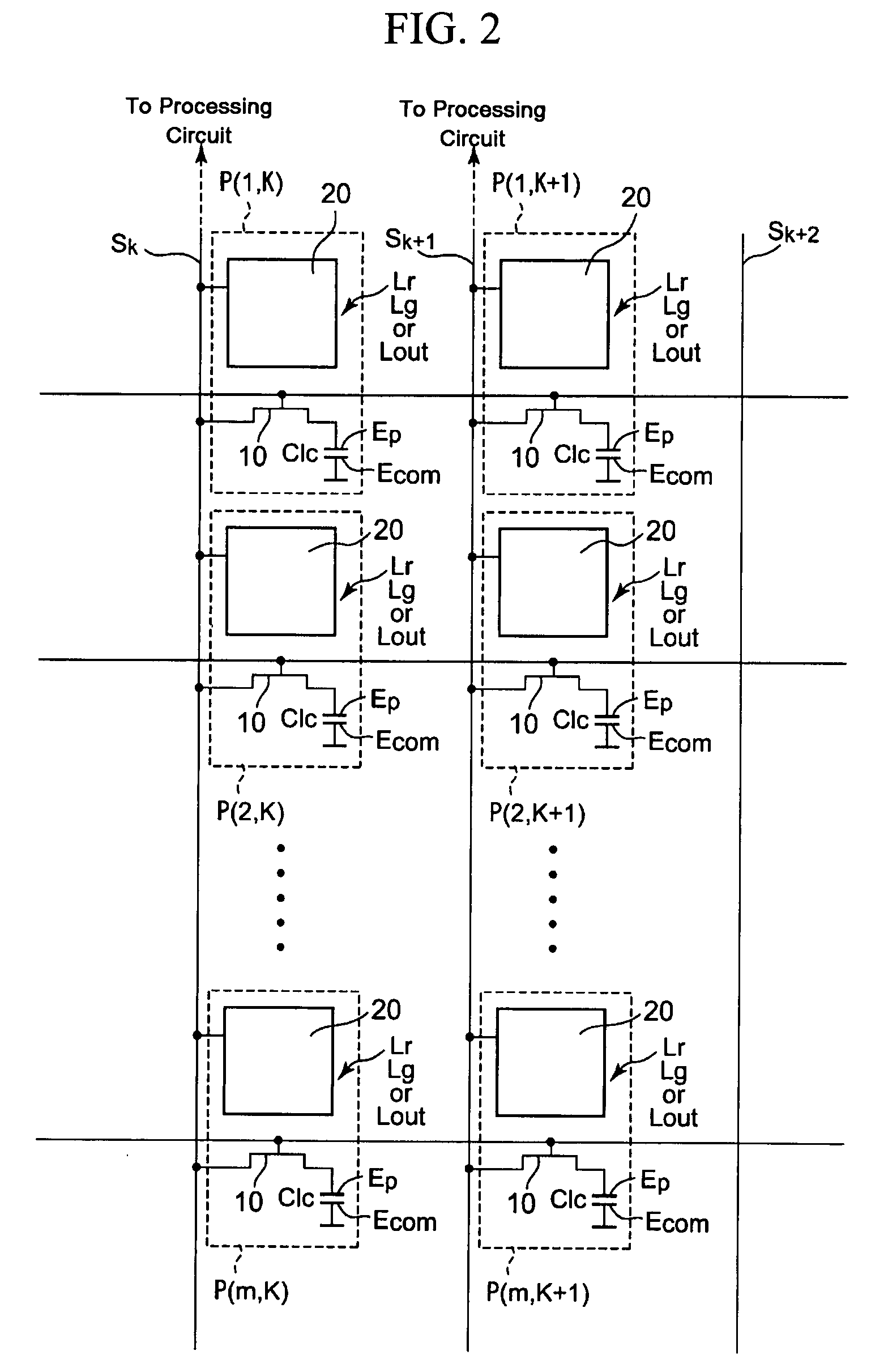
[0069]FIG. 5 is one example of a schematic diagram showing pixels of the display device 1 of second embodiment, the pixels arranged in matrix pattern.

[0070]Each pixel has a pixel switch 10, liquid crystal capacitance Clc, and a fingerprint data capturing part 80. In the second embodiment, the fingerprint data capturing part 80 is connected to the pixel switch 10 and the liquid crystal capacitance Clc instead of the source line, which is different manner from the first embodiment.

[0071]FIG. 6 is one example of a circuit diagram of one pixel in which a fingerprint data capturing part 80 shown in FIG. 5 is illustrated in detail.

[0072]The fingerprint data capturing part 80 comprises a photodiode 61. The diode 61 is connected to the power supply Vdd at its cathode and is connected to a sample switch 62 at i...


PUM

PropertyMeasurementUnit
voltagesaaaaaaaaaa
voltagesaaaaaaaaaa
voltageaaaaaaaaaa

Abstract

A display device which can authenticate fingerprint without a fingerprint sensor device and can be prevented from large size or reduced the size. A display device (1) is provided with a pixel or sub pixel comprising a photo diode (11) for detecting a light from a object, a holding capacitor (13) for holding a voltage (Vn1) corresponding to an intensity of the light detected by the photo diode (11), and a refreshing means (18) for writing a voltage (Vdd or Vss) into the holding capacitor (13) (node N1) on the basis of the voltage Vn1 held in the holding capacitor (13).

Description

TECHNICAL FIELD[0001]The invention relates to a display device comprising a sub pixel or a pixel.BACKGROUND ART[0002]In recent years, various data have been easily transmitted and received using a display device such as a mobile phone and a personal computer, as the Internet grows rapidly. There are many cases where data to be transmitted and to be received contain personal information. Therefore, if the third party saw the personal information stored in the mobile phone or the personal computer, the personal information might be abused. In order to prevent such abuse, for example, a method is used in which you can not use the display device unless a valid password is entered. However, if the password were seen by the third party, the personal information might be abused. Therefore, a fingerprint sensor device and a display device with a fingerprint sensor start to become widespread.DISCLOSURE OF INVENTIONTechnical Problem[0003]However, a problem of the conventional display device w...

Claims


Application Information

Patent Timeline
Patent Type & Authority Applications(United States)
IPC IPC(8): G06F3/042G02F1/133G06T1/00G09G3/20G09G3/36H04N5/335H04N5/369H04N5/374
CPCG06K9/0004G06V40/1318
Inventor YAMASHITA, KEITARO
Owner TPO HONG KONG HLDG
Why Eureka
Try Eureka