
Stereoscopic three dimensional visualization system and method of use

a three-dimensional visualization and visualization system technology, applied in the field of stereoscopic three-dimensional visualization system, can solve the problems of difficult for the assistant to accommodate with normal working posture, the depth of the assistant's stereoscopic optical image may be artificially shallow, and the back and neck pain can be difficult to cope with normal working postur

Active Publication Date: 2008-11-13
MORA ASSAD F +2
View PDF21 Cites 58 Cited by
  • Summary
  • Abstract
  • Description
  • Claims
  • Application Information

AI Technical Summary

Benefits of technology

[0014]Advantageously, as indicated above, by utilizing a common camera and creating two images rotated by a predetermined angle from one another, the image provided to both the operator and the assistant substantially replicate their respective views of a working environment, such as an oral cavity. Thus, neither the operator nor the assistant are forced to work from a stereoscopic image that is substantially rotated relative to their actual position. Further, by eliminating the ocular unit and various other components associated with a surgical microscope, the size of the stereoscopic device is reduced and the need to bend or otherwise crane to view the working environment through an ocular unit is eliminated.
[0015]Additionally, by replacing the ocular unit with the camera system described herein, a dental assistant is provided with the ability to view the working environment at the same point of focus as the operator without any concern of the operator unexpectedly moving the ocular unit, resulting in the ocular unit moving toward or away from the assistant's eyes.
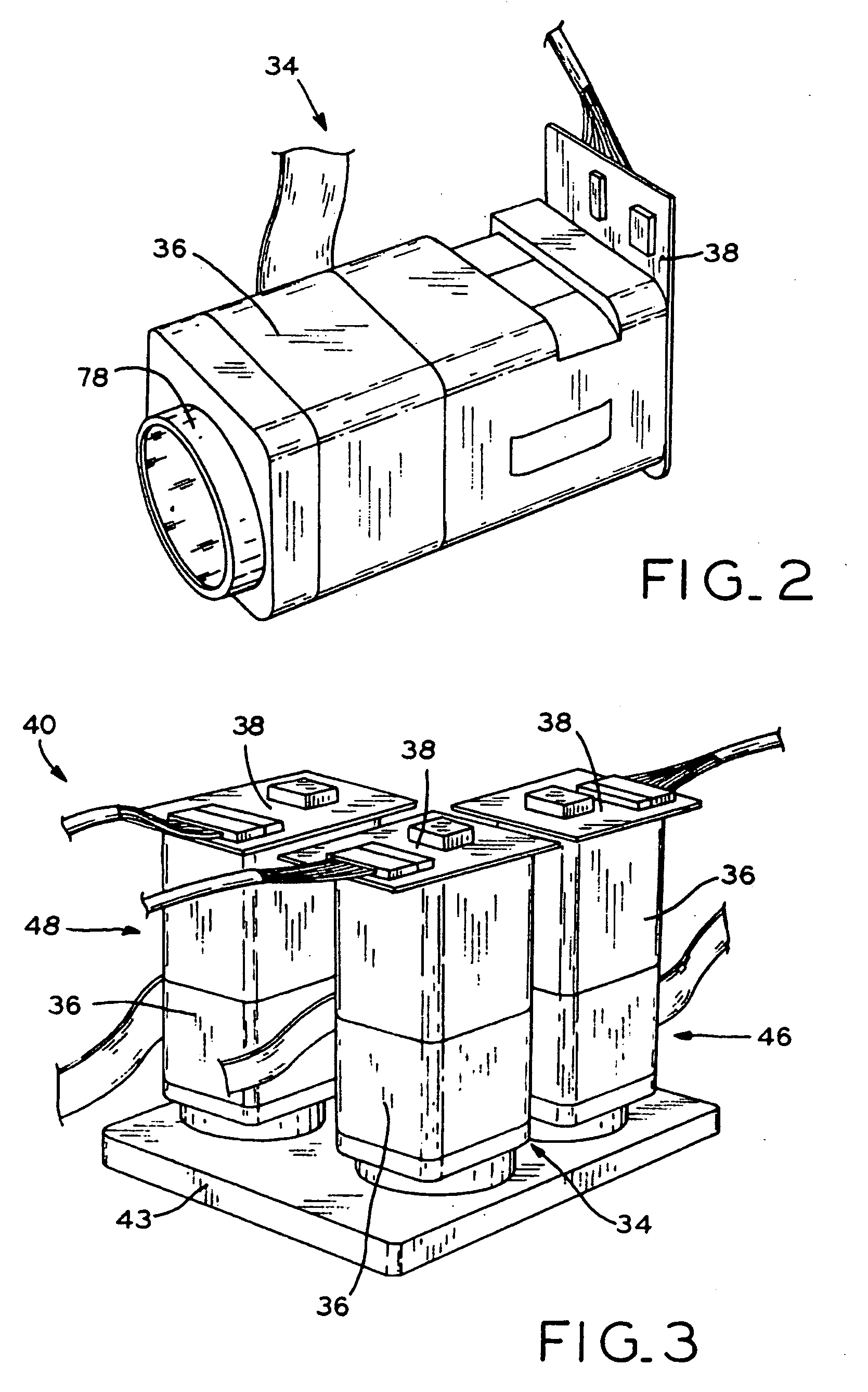
[0018]In yet another form thereof, the present invention provides a method of creating a stereoscopic visualization system for medical applications, including: providing three cameras having a lens pack and an imager; realigning the imager with the lens pack to align the center of the imager with the center of the lens pack; aligning each of the three cameras to have a substantially similar focal point; and securing each of the three cameras in position.

Problems solved by technology

Due to the repetitive leaning and craning, chronic back and neck pain may result.
Frequently, the co-observation tube might be moved by the dentist in a manner that makes it difficult for the assistant to accommodate with normal working posture, without the interruption for adjusting and repositioning the co-observation tube.
Moreover, even if the image generated for the assistant is optically rotated to provide the correct perspective, the depth of the assistant's stereoscopic optical image may be artificially shallow as a result of splitting only a single beam of the stereoscopic light path to generate the assistant's image.
As a result, the 3-D units are limited by the microscope design in their image generation, flexibility, and size.

Method used


Image

  • Stereoscopic three dimensional visualization system and method of use
  • Stereoscopic three dimensional visualization system and method of use
  • Stereoscopic three dimensional visualization system and method of use

Examples


Embodiment Construction

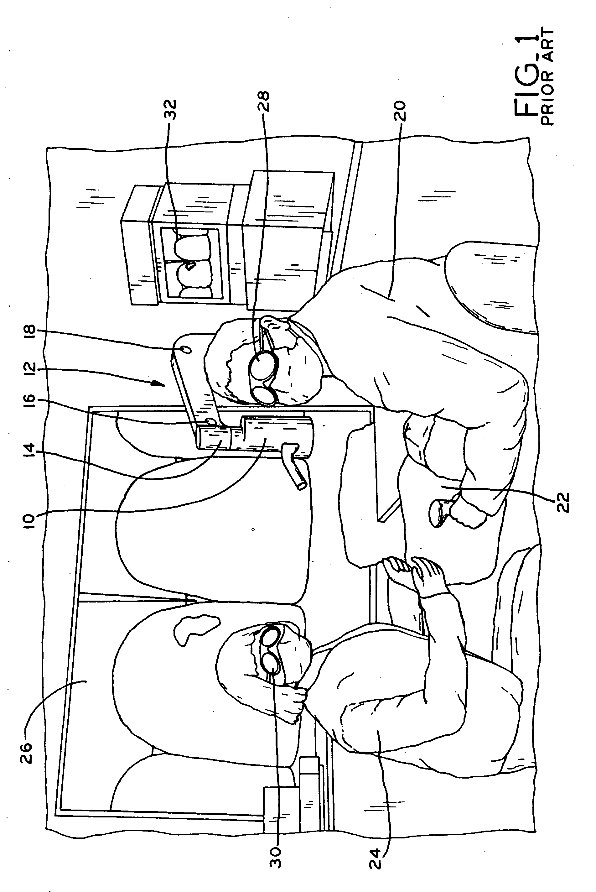
[0045]Referring to FIG. 1, a microsurgery theater is shown depicting prior art stereomicroscope 10. The tubular unit of stereomicroscope 10, which forms the body of the microscope, is connected to stand 12 to provide for the movement of stereomicroscope 10 about a plurality of pivot points 14, 16, 18. For example, stand 12 may be a Model U microscope stand commercially available from Carl Zeiss. During a surgical procedure, light is received by stereomicroscope 10 through the tubular unit, which is connected to a video camera. The video camera receives the light transmitted through the tubular unit and then generates an image that is transmitted to a projector, for example. The projector projects the image generated by stereomicroscope 10 onto screen 26, which is positioned directly in front of dentist 20.

[0046]As shown, dentist 20 is positioned behind and above the head of patient 22. Dentist 20 may then work, e.g., perform a dental procedure, from the image on screen 26, which, wi...


PUM


Abstract

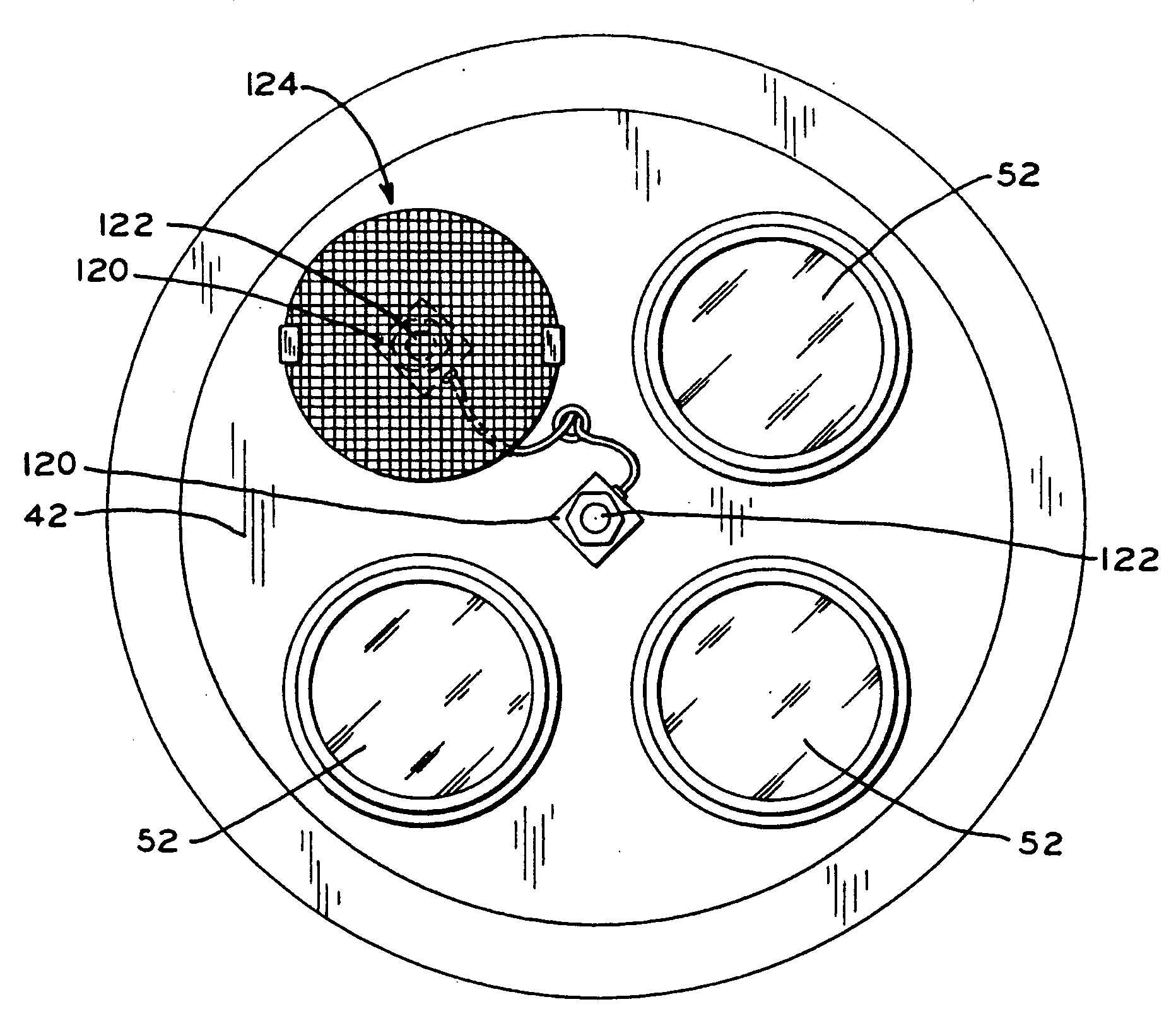
The present invention relates to a stereoscopic three dimensional visualization system, and particularly to a stereoscopic three dimensional visualization system for microdentistry, microsurgery, or industrial applications. In one exemplary embodiment, the present invention provides a plurality of cameras configured to provide a first stereoscopic image to a dentist or other professional and a second stereoscopic image to an assistant that has approximately the same focal point, but that is rotated by a predetermined angle from the first stereoscopic image. In one exemplary embodiment three cameras are utilized to create the stereoscopic images.

Description

CROSS-REFERENCE TO RELATED APPLICATIONS[0001]This application claims the benefit under Title 35 U.S.C. § 119(e) of U.S. Provisional Patent Application Ser. No. 60 / 928,597, entitled STEREOSCOPIC THREE DIMENSIONAL VISUALIZATION SYSTEM AND METHOD OF USE, filed on May 10, 2007, the entire disclosure of which is expressly incorporated by reference herein.BACKGROUND[0002]1. Field of the Invention[0003]The present invention relates to a stereoscopic three dimensional visualization system, and, particularly, to a stereoscopic three dimensional visualization system for dentistry, surgery, or industrial applications.[0004]2. Description of the Related Art[0005]Chronic back and neck pain is a common ailment experienced by dentists as a result of their work environment. In order to see into the oral cavity, dentists generally sit above the head of a patient who is placed in a reclined position. For example, a dentist may sit along the right side of a patient adjacent to his / her head, e.g., at a...

Claims


Application Information

Patent Timeline
IPC IPC(8): H04N13/02
CPCH04N13/243H04N13/282H04N13/346H04N13/296H04N13/349H04N13/398
Inventor MORA, ASSAD F.HARDY, ART H.WILSON, KITCHENER CLARK
Owner MORA ASSAD F
Learn More