Camera module

a technology of camera module and module, applied in the field of camera module, can solve the problems of increasing loss cost, complicated configuration, and difficulty in continuously maintaining reliability, and achieve the effect of high heat resistance material

Inactive Publication Date: 2008-11-13
SAMSUNG ELECTRO MECHANICS CO LTD
View PDF6 Cites 67 Cited by
  • Summary
  • Abstract
  • Description
  • Claims
  • Application Information

AI Technical Summary

Benefits of technology

[0019]The present invention has been invented in order to overcome the above-described various disadvantages and problems of the conventional camera module. It is, therefore, an object of the present invention to provide a camera module capable of being directly surface mounted with being received on a main substrate of a mounting terminal in a state that a solder cream is interposed and passing through a reflow by mounting a high heat resistant wafer lens in a lens barrel and forming surface mounting pads on a substrate mounted an image sensor thereon.
[0020]Further, it is, therefore, another objection of the present invention to prevent the camera module from being deformed due to heat applied in the reflow when passing through the reflow for soldering-bonding of the substrate after being received on the main substrate by forming a lens and a lens barrel mounted the lens thereon and a housing coupled the lens barrel thereto with a high heat resistant material.

Problems solved by technology

Because in the conventional camera module with the above technical configuration, the leads 7 protruded outside the lens holder 4 are connected on a main substrate of a terminal, any connection device such as a connector or a socket to electrically connect the camera module is not required, however the configuration is complicated and also a normal operation is performed only when all the leads 7 are electrically connected to the imaging device 2 through the electrode 6, and therefore it is difficult to continuously maintain the reliability thereof.
Further, the method for manufacturing the conventional camera module is complicated and the imaging device 2, the substrate and a part of leads 7 are installed inside the integral lens holder 4 and thus, when connection error of the leads 7, the substrate 1 and the imaging device 2 occurs, there is nothing for it but to discard a finished product, thereby increasing a loss cost.

Method used


Image

  • Camera module
  • Camera module
  • Camera module

Examples


Embodiment Construction

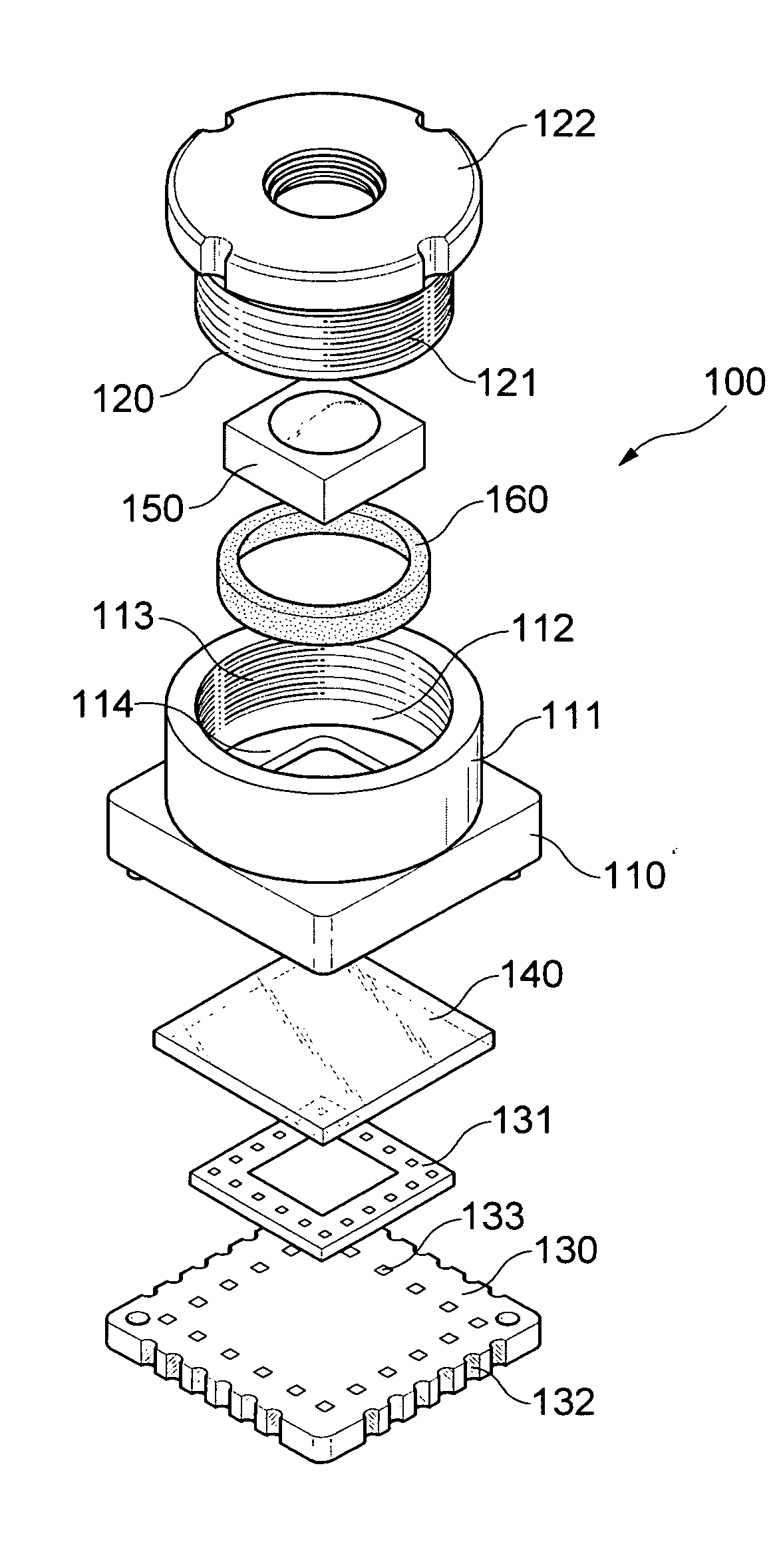
[0029]The objects of the present invention can be achieved by providing a camera module including a housing with a cylindrical barrel coupling unit extended upward from a central part of the housing, wherein an opening unit is formed on a top portion of the cylindrical barrel coupling unit; a lens barrel inserted through the opening unit of the barrel coupling unit; a wafer lens mounted in the lens barrel; and a substrate with an image sensor mounted on a top surface of the substrate by wire bonding and closely adhered to a lower part of the housing by being provided with surface mounting pads on each lateral surface thereof.

[0030]In the housing, a female screw unit is formed on an inner circumferential surface of the barrel coupling unit extended upward.

[0031]Further, the lens barrel coupled to the housing is formed in a cylindrical shape to be conformally combined in the barrel coupling unit and provided with a male screw unit on an outer circumferential surface.

[0032]And, a disk-...


PUM


Abstract

The present invention relates to a camera module capable of being surface mounted (SMT) on a main substrate.
In accordance with the present invention, the camera module includes a housing provided with a cylindrical barrel coupling unit extended upward from a central part of the housing, wherein a female screw unit is formed on an inner circumferential surface of the cylindrical barrel coupling unit and an opening unit is formed on a top portion of the cylindrical barrel coupling unit; a lens barrel provided with a male screw unit on an outer circumferential surface by being formed in a cylindrical shape to be conformally combined with the barrel coupling unit and screw-coupled to the female screw unit by being inserted through the opening unit of the barrel coupling unit; a wafer lens mounted in the lens barrel; and a substrate with an image sensor mounted on a top surface of the substrate by a wire bonding and closely coupled to a lower part of the housing by being provided with surface mounting pads on each lateral surface thereof and has advantages that the process for mounting the camera module onto the substrate is simplified and further a process cost is reduced by removing an additional connection device for electrically connecting the camera module to the main substrate.

Description

CROSS-REFERENCE TO RELATED APPLICATIONS[0001]This application claims the benefit of Korean Patent Application No. 10-2007-0045658 filed with the Korea Intellectual Property Office on May 10, 2007, the disclosure of which is incorporated herein by reference.BACKGROUND OF THE INVENTION[0002]1. Field of the Invention[0003]The present invention relates to a camera module capable of being surface mounted (SMT) on a main substrate; and, more particularly, to a camera module capable of being surface mounted on a main substrate by using a solder cream with passing through a reflow by mounting a wafer lens in a lens barrel and forming pads in a lower part of a substrate closely adhered to a lower part of a housing.[0004]2. Description of the Related Art[0005]Currently, when producing a motor car and an endoscope or the like including IT (Information Technology) equipment such as a mobile communication terminal, a PDA (Personal Digital Assistant) and a MP3 player or the like, a camera module ...

Claims


Application Information

Patent Timeline
Patent Type & Authority Applications(United States)
IPC IPC(8): H04N5/225
CPCG02B7/022G03B17/12H01L27/14618H04N5/2253H04N5/2254H04N5/2257H01L2224/48091H01L2224/48227H04N23/57H04N23/54H04N23/55H01L2924/00014G02B7/02
Inventor CHO, JAE SUBKIM, JUNG JINRYU, JIN MUNKIM, BO KYOUNG
Owner SAMSUNG ELECTRO MECHANICS CO LTD
Why Eureka
Try Eureka