High Frequency Optical Millimeter-Wave Generation and Wavelength Reuse

Active Publication Date: 2008-11-13
NEC CORP
View PDF2 Cites 20 Cited by
  • Summary
  • Abstract
  • Description
  • Claims
  • Application Information

AI Technical Summary

Problems solved by technology

However, this technique cannot provi

Method used


Image

  • High Frequency Optical Millimeter-Wave Generation and Wavelength Reuse
  • High Frequency Optical Millimeter-Wave Generation and Wavelength Reuse
  • High Frequency Optical Millimeter-Wave Generation and Wavelength Reuse

Examples


Embodiment Construction

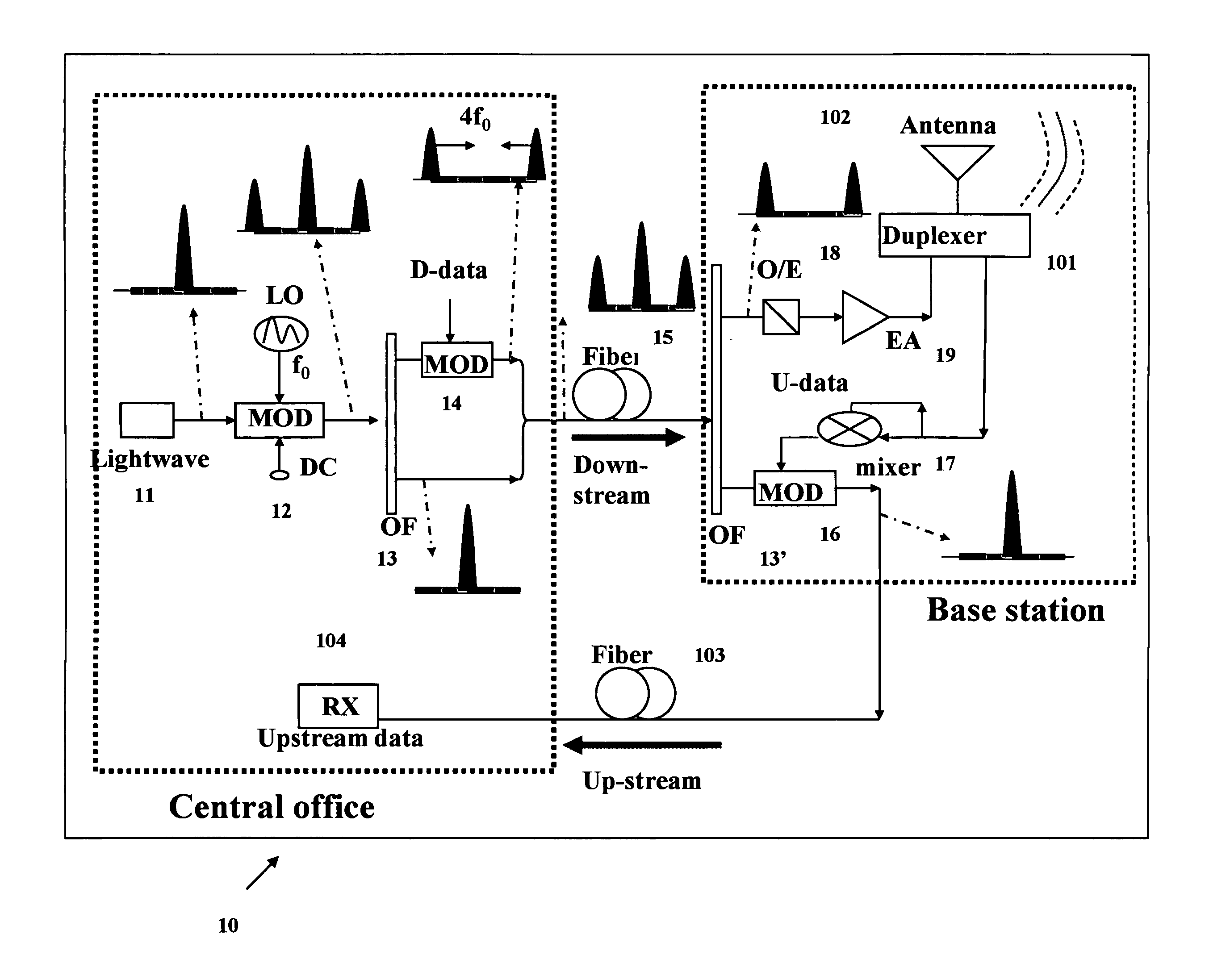
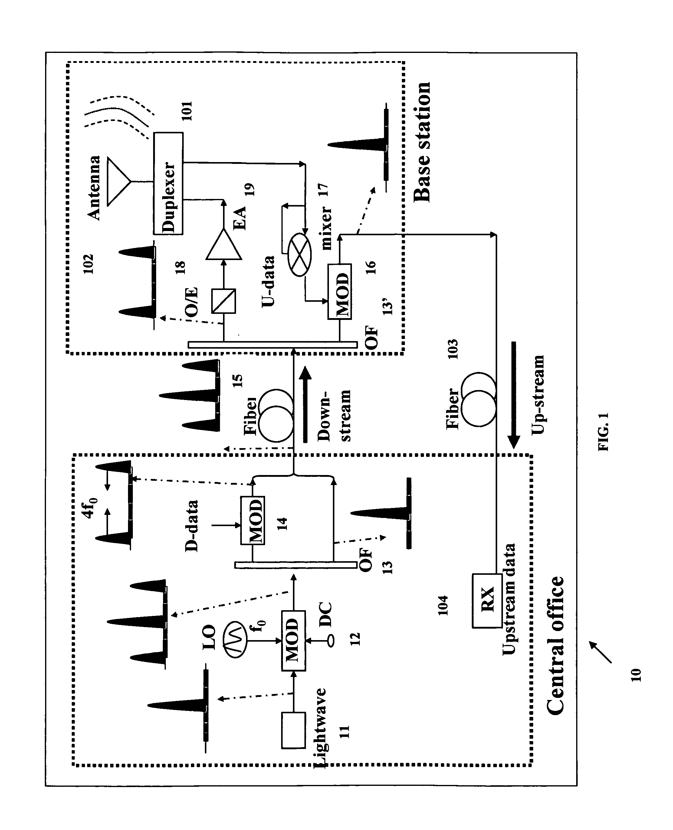
[0010]The application is directed to generating a centralized lightwave for full-duplex ROF architecture while generating a high-frequency millimeter wave (mm-wave) with multiple double-frequency of that of the LO signal, using the inventive technique for generating optical mm-wave signals.

[0011]Referring to the block diagram 10, FIG. 1, there is shown an exemplary radio on fiber configuration including a lightwave source 11; a local oscillator LO at frequency fo; external modulators (MOD), 12, 14, 16; a direct current (DC) 12; optical filters OF 13, 13′; downstream data, D-data; a downstream transmission fiber 15; upstream data, U-data; mixer 17, optical-to-electrical converter, OE 18; electrical amplifier, EA, 19; duplexer 101, antenna 102, up-stream fiber 103; and receiver, RX, 104.

[0012]Referring again to FIG. 1, an LiNbO3 external modulator MOD 12,14 and a cascaded optical filter 13 are employed to generate an optical millimeter wave (mm-wave) which is also used to providing a ...


PUM


Abstract

A method includes generating an optical millimeter wave signal for modulation of a first data signal, and deriving from the generated optical millimeter wave signal a subsequent light source for modulation of a second data signal. More specifically the generating includes modulating a light wave to a multiple of a frequency of an oscillating signal. Alternatively, the generating includes modulating a data signal mixed with an oscillating signal to a multiple of a frequency of the oscillating signal. The deriving includes modulating a frequency component filtered from a data modulation of the generated optical millimeter wave signal.

Description

[0001]This application claims the benefit of U.S. Provisional Application No. 60 / 916,632, entitled “Centralized Lightwave Radio-Over-Fiber System with High-Frequency Optimal Millimeter-Wave Generation by Low-Frequency and Low-Bandwidth Optical and Electrical Sources”, filed on May 8, 2007, the contents of which is incorporated by reference herein.BACKGROUND OF THE INVENTION[0002]The present invention relates generally to optical communications and, more particularly, to high frequency optical millimeter wave generation and wavelength reuse.[0003]To construct a simple base station and to generate a low-cost optical millimeter wave (mm-wave) there are two key technologies required to make radio-over-fiber (ROF) systems practical for commercial deployment. Schemes of wavelength reuse or centralized lightwave in a central office have been proposed and experimentally demonstrated. The common characteristic in the previous scheme is that the electrical local oscillator (LO) frequency for ...

Claims


Application Information

Patent Timeline
IPC IPC(8): H04B10/00H04B10/04
CPCH04B10/25758
Inventor YU, JIANJUNQIAN, DAYOUXU, LEIWANG, TING
Owner NEC CORP
Why Eureka
Try Eureka