Phased antenna array with electro-optic readout circuit with multiplexing and MLL and related methods

a phased array and readout circuit technology, applied in the field of phased antenna arrays, can solve the problems of complex phased array antennas, high manufacturing costs, and limited beam bandwidth and beam beam limit of phased array antennas, and achieve the effect of effective operation

Inactive Publication Date: 2013-07-11
HARRIS CORP
View PDF6 Cites 15 Cited by
  • Summary
  • Abstract
  • Description
  • Claims
  • Application Information

AI Technical Summary

Benefits of technology

[0007]In view of the foregoing background, it is therefore an object of the present invention to provide a phased antenna array that can operate effectively at high frequencies.

Problems solved by technology

For example, millimeter wave, i.e. extremely high frequency (EHF), phased array antennas may be complex and costly to manufacture.
Furthermore, these phased array antennas may be limited in bandwidth and the number of beams.

Method used


Image

  • Phased antenna array with electro-optic readout circuit with multiplexing and MLL and related methods
  • Phased antenna array with electro-optic readout circuit with multiplexing and MLL and related methods
  • Phased antenna array with electro-optic readout circuit with multiplexing and MLL and related methods

Examples


Embodiment Construction

[0019]The present invention will now be described more fully hereinafter with reference to the accompanying drawings, in which preferred embodiments of the invention are shown. This invention may, however, be embodied in many different forms and should not be construed as limited to the embodiments set forth herein. Rather, these embodiments are provided so that this disclosure will be thorough and complete, and will fully convey the scope of the invention to those skilled in the art. Like numbers refer to like elements throughout, and prime notation is used to indicate similar elements in alternative embodiments.

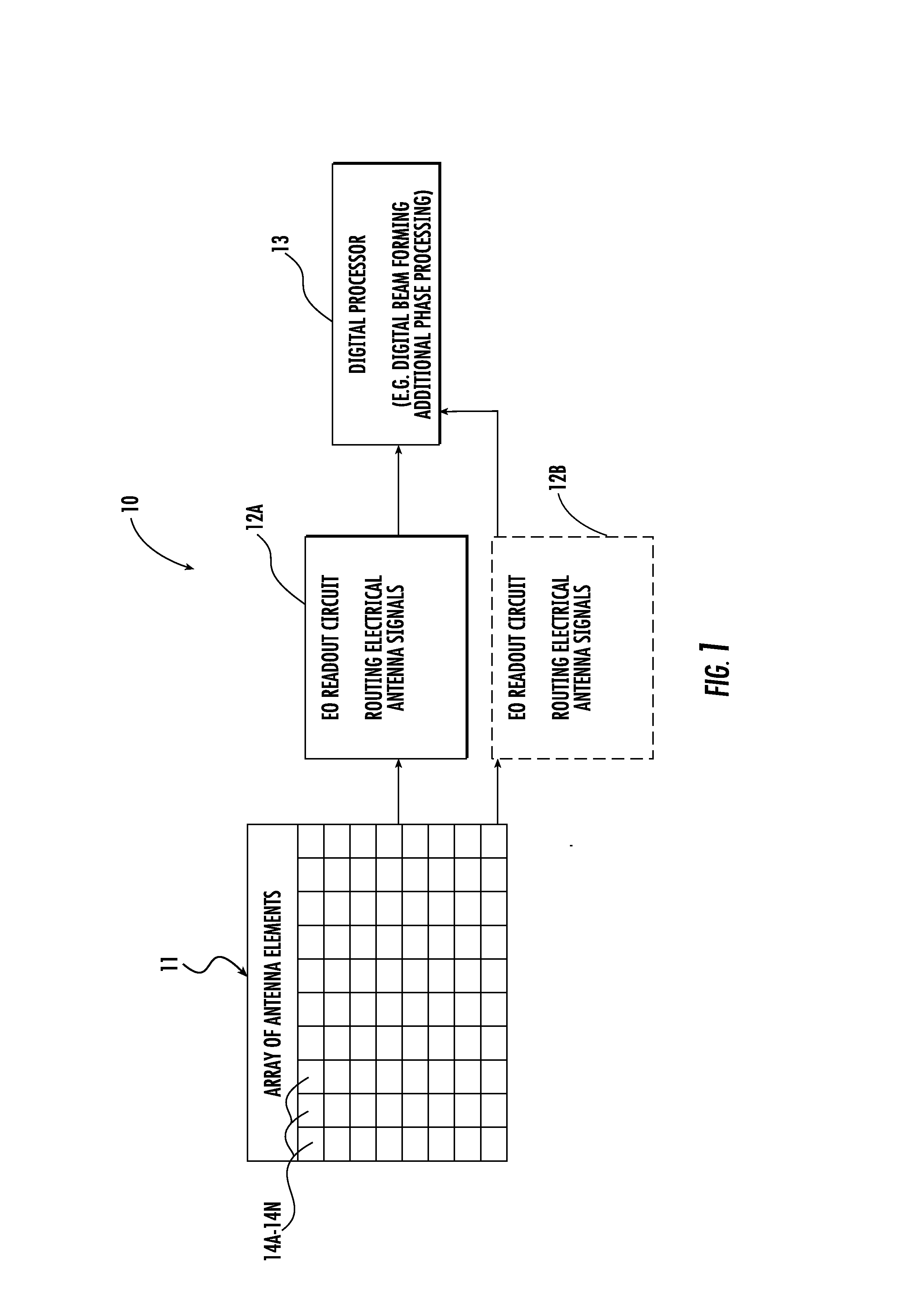
[0020]Referring initially to FIG. 1, a phased antenna array system 10 according to the present invention is now described. The phased antenna array system 10 illustratively includes an array 11 of antenna elements 14a-14n. As will be appreciated by those skilled in the art, the array 11 of antenna elements is illustrated in a square shape, but could take other shapes, such ...


PUM


Abstract

A phased antenna array includes an array of antenna elements, and an electro-optic (EO) readout circuit coupled to the array of antenna elements. The EU readout circuit includes an optical source including a mode locked laser (MLL) configured to generate an optical carrier signal having beam carrier wavelengths, an EO modulator configured to modulate a signal from an antenna element based upon the optical carrier signal, a first WDM coupled downstream from the EO modulator, and optical-to-electrical converters coupled downstream from the first WDM. The first WDM is configured to multiplex each modulated beam carrier wavelength to a respective optical-to-electrical converter.

Description

FIELD OF THE INVENTION[0001]The present invention relates to the field of phased antenna arrays, and, more particularly, to phased antenna arrays with optical components and related methods.BACKGROUND OF THE INVENTION[0002]Wireless communications devices are an integral part of society and permeate daily life. The typical wireless communications device includes an antenna, and a transceiver coupled to the antenna. The transceiver and the antenna cooperate to transmit and receive communications signals.[0003]One particularly advantageous antenna type is the phased array antenna. The phased array antenna comprises a plurality of antenna elements, and processing circuitry to vary the related phase of the signals received from the individual antenna elements. The varying of the related phase of the antenna elements may provide for changing the effective radiation pattern of the antenna. In particular, the radiation pattern can be changed to be highly directional, i.e. reinforcing signal...

Claims


Application Information

Patent Timeline
Patent Type & Authority Applications(United States)
IPC IPC(8): H04J14/02
CPCH04J14/02H04B2210/006H04B10/90
Inventor MIDDLETON, CHARLESMAST, ALANKRALOVEC, JAYDESALVO, RICHARDDEIBNER, GUS W.
Owner HARRIS CORP
Why Eureka
Try Eureka