Wavelength multiplexer/demultiplexer

a multi-multi-plexer and wavelength technology, applied in the field of wavelength multi-demultiplexers, can solve the problems of affecting spectral degradation, the wavelength response around the edge wavelength from the pass band to the reflection band may not be good enough, etc., to achieve good wavelength response, reduce the effect of separation and good wavelength respons

Active Publication Date: 2006-02-02
NIPPON TELEGRAPH & TELEPHONE CORP
View PDF2 Cites 13 Cited by
  • Summary
  • Abstract
  • Description
  • Claims
  • Application Information

AI Technical Summary

Benefits of technology

[0025] More specifically, in the present invention, spectral characteristic in the reflection path becomes nearly rectangular shape in the range of the distance X being from 0 to d/2, and reflection loss does not excessively increase on the longer-wavelength side of the edge wavelength of the reflection band. That is, there exists no minimum loss of the peak P, which is outstanding in the prior art embodiment shown in FIG. 15.
[0026] Furthermore, in the present invention, the spectral characteristic in the reflection pa

Problems solved by technology

Also, it is required to increase the thickness of the dielectric multilayer to narrow the separation spacing, which leads to affect spectral degradation due to the divergent light furthermore.

Method used


Image

  • Wavelength multiplexer/demultiplexer
  • Wavelength multiplexer/demultiplexer
  • Wavelength multiplexer/demultiplexer

Examples


first embodiment

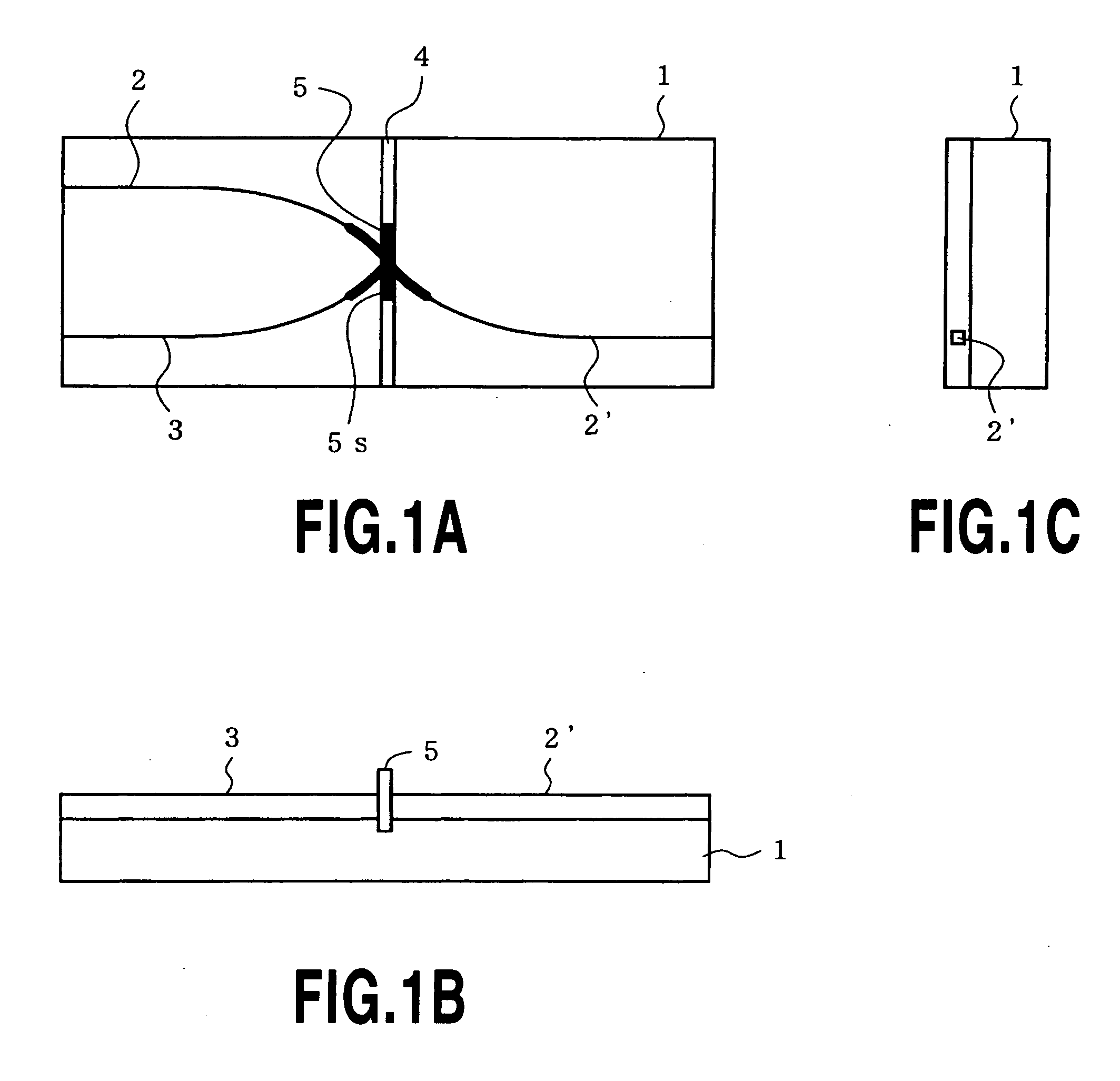
[0048]FIG. 1A is a plane view showing a wavelength multi / demultiplexer 100 according to the first embodiment of the present invention, and FIGS. 1B and 1C are, respectively, a front view and a right side view thereof.

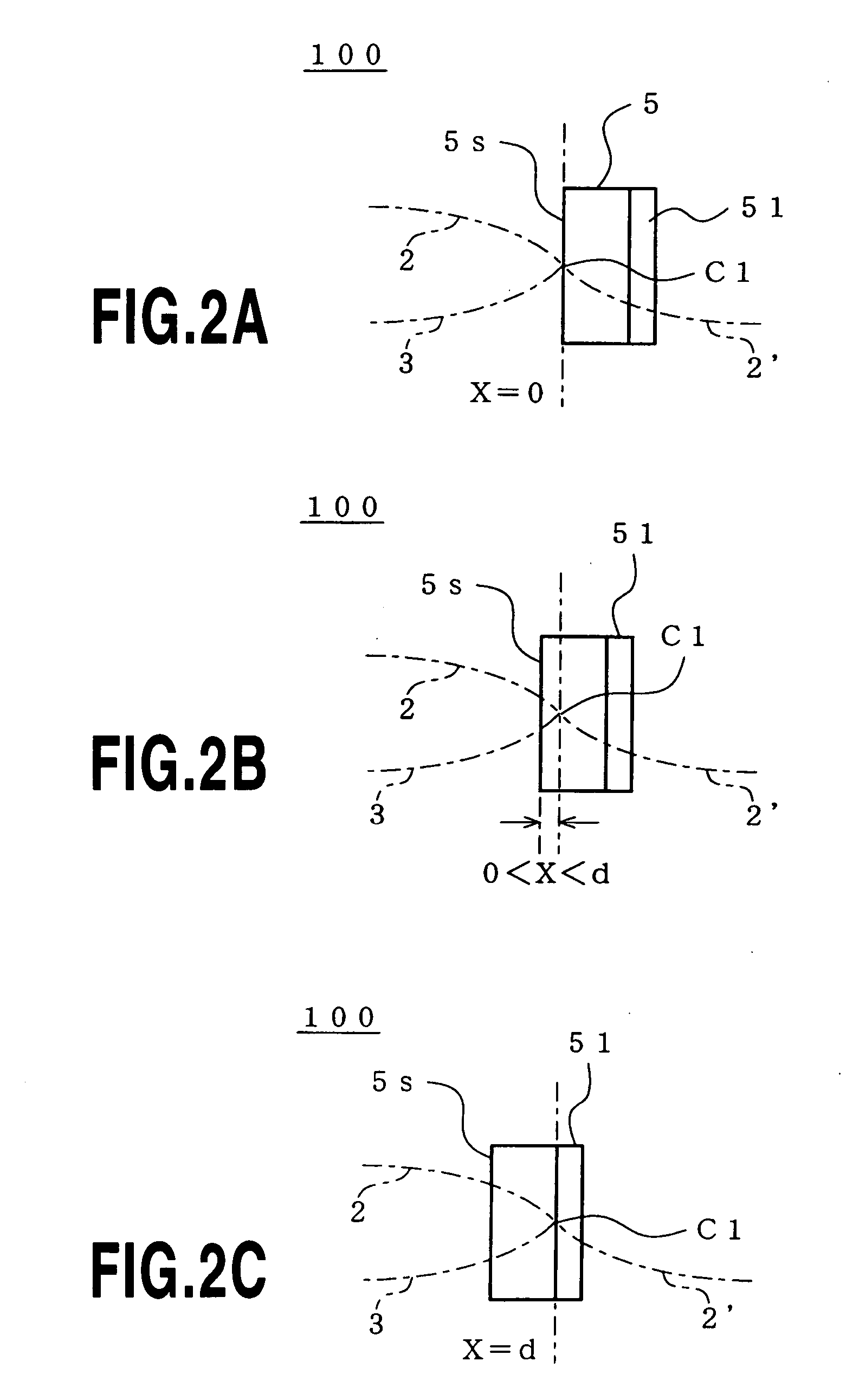
[0049]FIG. 2A is an illustration of a positional relationship, in the wavelength multi / demultiplexer 100, where the distance X from a multilayer surface 5s of a dielectric multilayer filter 5 to an intersection point C1 of optical waveguides 2 and 3 is 0. Furthermore, FIGS. 2B and 2C are illustrations of positional relationships, showing respectively where the distance X is ranging from 0 to d and the distance X is d, respectively.

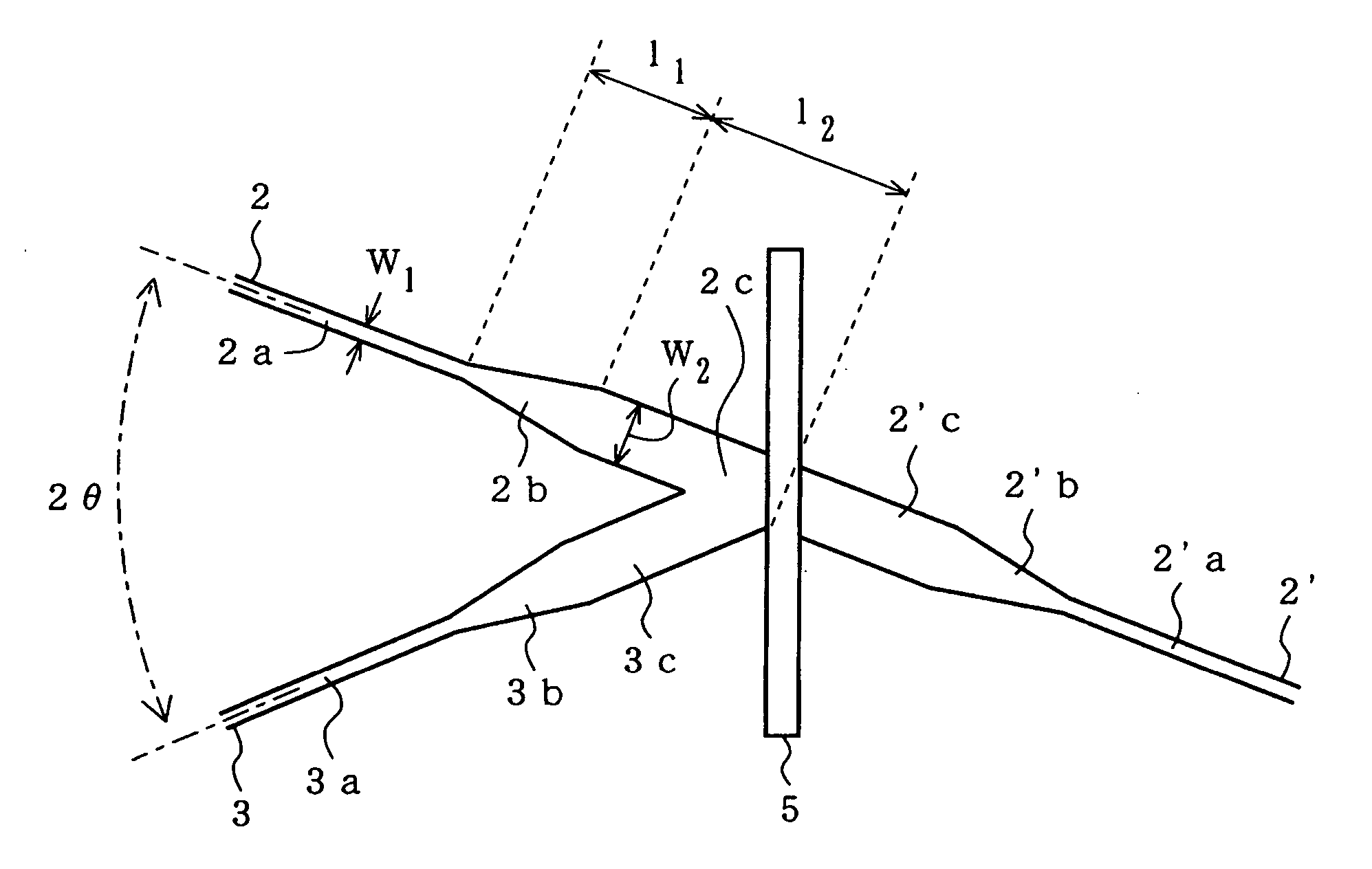
[0050] The wavelength multi / demultiplexer 100 comprises a silicon substrate 1, single-mode optical waveguides 2, 3 and 2′, a groove 4, and a dielectric multilayer filter 5.

[0051] The single-mode optical waveguides 2, 3 and 2′ comprise a core and a clad made of silica-based glass. The dielectric multilayer filter 5 is placed within the groov...

second embodiment

[0123]FIG. 13 is an illustration of a wavelength multi / demultiplexer 200 according to the second embodiment of the present invention, and shows the vicinity of a dielectric multilayer filter 5 (vicinity of an intersection point C1 of optical waveguides).

[0124] The configuration of the wavelength multi / demultiplexer 200 is basically the same as that of the wavelength multi / demultiplexer 100, except that an optical waveguide 3′ is provided in the point symmetric position to the output optical waveguide 3.

[0125] The output optical waveguide 3′ consists of an output optical waveguide 3′a, a tapered optical waveguide 3′b, and an enlarged optical waveguide 3′c. That is, the width of the output optical waveguide 3′a is enlarged through the tapered optical waveguide 3′b and connected to the enlarged optical waveguide 3′c.

[0126] In addition, the optical waveguide 3′ may be used as a monitoring terminal, etc., or it may be used as an open terminal.


PUM


Abstract

Disclosed is a wavelength multi/demultiplexer for separating two wavelength bands with a narrow wavelength spacing. A dielectric multilayer filter is provided in an intersection portion where two optical waveguides intersect each other and separates incident light to the dielectric multilayer filter to transmitted light and reflected light. Here, the distance X from the multilayer surface on the light-incident side of the dielectric multilayer to the central intersection point of the two intersecting optical waveguides is arranged to satisfy 0≦X≦d/2 (where “d” represents the thickness of the dielectric multilayer). With this configuration, a multi/demultiplexer can be realized that shows good wavelength response without spectral degradation even for two wavelengths having narrow wavelength spacing.

Description

TECHNICAL FIELD [0001] The present invention relates to a wavelength multi / demultiplexer used in an optical communication, and particularly to an optical wavelength multi / demultiplexer capable of separating two wavelength bands having a narrow wavelength spacing, with a simple configuration. cl BACKGROUND ART [0002] An optical wavelength division multiplexing (WDM) system for transmitting light of multiple wavelengths through a single transmission line has been used to realize high-capacity transmission and / or simultaneous bidirectional transmission. In a WDM system, there are a variety of multi / demultiplexers for combining and / or separating multiplexed light, and a low-cost device is required for such multi / demultiplexers used in subscriber (access) systems. [0003]FIG. 14 shows a conventional wavelength multi / demultiplexer 500. [0004] The conventional wavelength multi / demultiplexer 500 is a low-cost device, which combines and / or separates two wavelengths of 1.3 μm and 1.55 μm (see ...

Claims


Application Information

Patent Timeline
IPC IPC(8): G02B6/12G02B6/34
CPCG02B6/12007G02B2006/12109G02B6/2938G02B6/29368
Inventor YANAGISAWA, MASASHIROOGUCHI, TAISUKEINOUE, YASUYUKIHIBINO, YOSHINORIHIDA, YASUHIROISHII, MOTOHAVA
Owner NIPPON TELEGRAPH & TELEPHONE CORP
Why Eureka
Try Eureka