Eureka AIR delivers breakthrough ideas for toughest innovation challenges, trusted by R&D personnel around the world.

Fluidification device for granular material

Inactive Publication Date: 2008-11-13
MORETTO SPA
View PDF10 Cites 24 Cited by
  • Summary
  • Abstract
  • Description
  • Claims
  • Application Information

AI Technical Summary

Benefits of technology

[0015]The main object of the present invention is to provide a new fluidification device for fluidifying poorly flowing granular materials, which is suitable for eliminating or drastically reducing the drawbacks referred to above with reference to the state of the art.
[0016]Another object of the present invention is to provide a fluidification device to be installed in a container or loading hopper for a granular material, which allows regular fall or descent of the granules in the hopper, thereby assuring a regular and continuous withdrawal of granular material from a lower discharge mouth without generating vibrations that would damage any handling or measuring systems associated with, or adjacent to, the loading hopper.
[0017]Not least object of the present invention is to provide a fluidification device which is highly reliable, easily installable in a loading hopper and can be obtained at competitive production and service costs.

Problems solved by technology

However, the granules of the loose material may have an irregular shape, e.g. a flat shape, high friction and / or large volume / surface ratio, i.e. configuration features that contribute to make flowing within a loading hopper difficult and sometimes impossible.
Moreover, in case of high friction between stored granular material and the walls of the loading hopper, a substantial wall effect is generated with consequent increase in falling rate differancies between the granules close to the hopper walls, especially when the walls are convergent, and the granules relatively far away from the walls.
Moreover, conventional “bridge breaker” systems have a number of undesired drawbacks in that they cause irregular delivery of granular material from the discharge mouth of the loading hopper, i.e. at a flow rate highly variable in time.
Furthermore, vibrations generated by the “bridge breaker” system are transmitted not only to the loading hopper, but also to the rest of the working plant, and thus, if for example the plant comprises a weighing system, measured altered, and thus not reliable values are obtained.
Materials also exist, however, that are insensitive to conventional “bridge breaker” systems and thus make it impossible delivery through the discharge mouth of the loading hopper.
On the other hand, it is impossible to subject such materials to a grinding operation that could result in a finer granular size, as this would cause excessive degradation of the polymeric material.
Flowing problems in storage containers also arise in plants for processing granular materials of a nature different from plastics.

Method used


Image

  • Fluidification device for granular material
  • Fluidification device for granular material
  • Fluidification device for granular material

Examples


Embodiment Construction

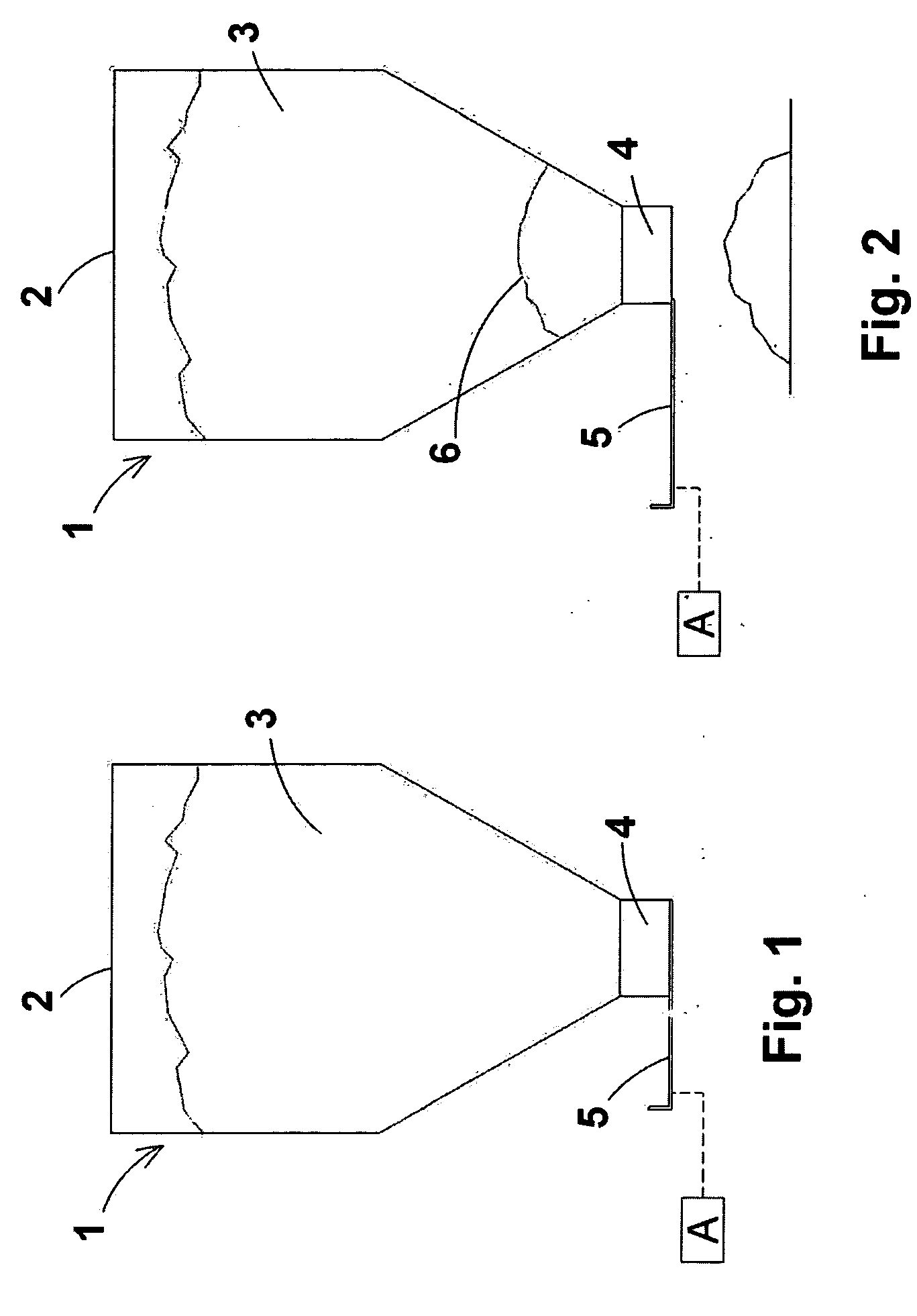
[0032]Referring first to FIGS. 1 and 2, there is illustrated a loading hopper 1 with no “bridge breaker” system and having a relatively large upper opening 2 for loading granular material 3, a relatively narrow lower discharge mouth 4 for delivering material loaded therein and opening-closing means 5 for the discharge mouth 4, e.g. a gate valve, preferably driven by an actuator 16 of any suitable type, e.g. through a pinion-rack mechanism driven by an electric motor (not shown in drawings).

[0033]Preferably, the actuator 16 can be controlled by an electronic control unit CU, typically a programmable electronic board.

[0034]More particularly, as illustrated in FIG. 1, the lower discharge mouth 4 is closed by the gate valve 5 and holds the granular material 3 in the loading hopper 1. When the gate valve 5 of the discharge valve 4 of the loading hopper 1 is opened, as illustrated in FIG. 2, the granular material 3 can come out therethrough, but especially owing to cohesion, compaction, e...


PUM


Abstract

A fluidification device for granular material comprising a loading hopper (10) for granular material (30) provided with a lower discharged mouth (40) and an opening-closing device (50) for the discharge mouth (40), in which the walls of the loading hopper (10) presents holes for a respective jet means (70a-70f) designed to direct into the loading hopper (10) a jet (g) of pressurized fluid delivered by intermittent pressurized-fluid supplying means in fluid communication with each jet means (70a-70f).

Description

FIELD OF INVENTION[0001]The present invention relates to a fluidification device for granular material, particularly useful for fluidifying granular plastics contained in a loading hopper.BACKGROUND OF INVENTION[0002]In the field of processing plastics materials, the raw material is a loose material, i.e. in granules, and is stored in storage containers of large size for being delivered by a supplier. The granular material is then transferred into containers of medium and small size, e.g. a loading hopper, for continuously feeding molding or processing machines arranged in a working plant to process or transform plastics granular material through various transformation stages.[0003]In the various working stages, as a matter of fact, various needs are to be met, e.g. dehumidification of the granules, such as for a number of hours, while the same are at rest, mixing of the granules with additives and / or dyes, as well as transfer of the granules to the load mouth of a processing machin...

Claims


Application Information

Patent Timeline
IPC IPC(8): B65G53/42
CPCB65D88/703B01J8/20B01J8/18
Inventor CRITELLI, FEDERICO
Owner MORETTO SPA
Why Eureka
Eureka Blog
Learn More