Fan and fan assembly

a technology of fan and assembly, which is applied in the direction of positive displacement liquid engine, piston pump, liquid fuel engine, etc., to achieve the effect of avoiding turbulence and vortex generation, enhancing fan efficiency, and extending the utility area of the circuit board

Active Publication Date: 2008-11-13
DELTA ELECTRONICS INC
View PDF14 Cites 19 Cited by
  • Summary
  • Abstract
  • Description
  • Claims
  • Application Information

AI Technical Summary

Benefits of technology

[0007]In view of the foregoing, the present invention is to provide a fan and a fan assembly having the improved arrangement of a circuit board without influencing the stability of air streams and having the enlarged air rail to enhance the efficiency of the fan.
[0010]As mentioned above, because the fan and the fan assembly of the present invention have a design that the circuit board is disposed on the external surface of the fan frame, i.e. the circuit board is not accommodated in the fan frame, the circuit board cannot influence the flowing direction of the air streams. Compared with the prior art, generation of the turbulence and the vortex can be avoided, and the efficiency of the fan can be enhanced. In addition, the circuit board is disposed outside the fan frame, and the utility area of the circuit board can be enlarged. Moreover, the number of the electronic components or the sizes of the electronic components disposed on the circuit board are not particularly restricted so that the structure design can become more flexible.

Problems solved by technology

However, such a design accompanies the larger current for driving the motor to rotate.

Method used


Image

  • Fan and fan assembly
  • Fan and fan assembly
  • Fan and fan assembly

Examples


first embodiment

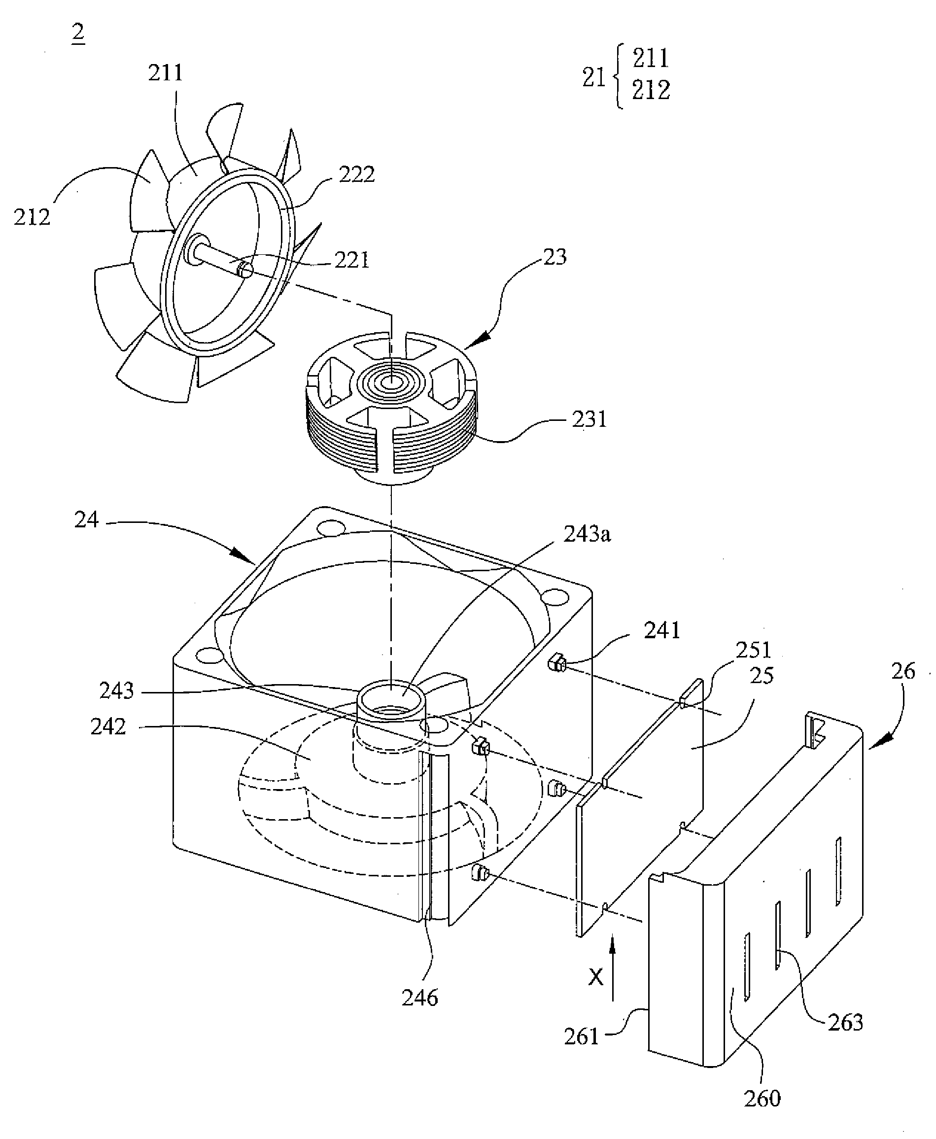
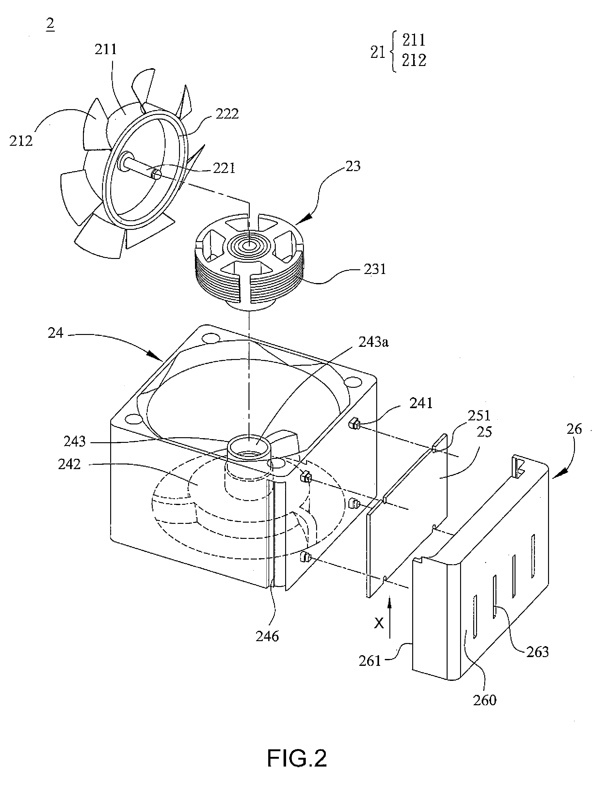
[0018]FIG. 2 is a schematic illustration showing a structure of a fan 2 according to the present invention. Referring to FIG. 2, the fan 2 includes an impeller 21, a motor 23 and a fan frame 24. The impeller 21 includes a hub 211 and a plurality of blades 212 disposed around the hub 211, and there is a rotating shaft 221 connected to the hub 211. The magnetic element 222 is disposed and attached on an inner surface of the hub 211. The magnetic element 222 can be, for example, a permanent magnet, or an electronic magnet. The motor 23 is for driving the impeller 21 to rotate, and the motor 23 includes several silicon steel sheets stacked together and then a coil is wound around these silicon steel sheets. Also, the silicon steel sheets are disposed with respect to the magnetic element 222.

[0019]As mentioned hereinabove, the base 242 has a bearing tube 243 and the base 242 is for supporting the motor 23. When the motor 23 and the impeller 21 are assembled, the rotating shaft 221 is dis...

second embodiment

[0027]FIG. 5 is a structure schematic illustration showing another fan assembly 5 according to the preferred embodiment of the present invention. As shown in FIG. 5, the fan assembly 5 includes two fans 3. The number of the fans 3 constituting the fan assembly is not restricted to that shown in FIG. 5, and can be adjusted according to the actual requirements. The structure and the function of each fan 3 are similar to those of the fan of the second embodiment, so detailed descriptions thereof will be omitted. Each fan 3 of the fan assembly 5 has a connecting member 56, which has at least one opening 561. Fan frames 54 of the two fans are connected together so that the common circuit board 55 is disposed in a closed space formed after the two connecting members 56 are combined together to protect the circuit board 55 and the electronic components disposed on the circuit board 55. In addition, the fan assembly 5 of this embodiment has a plurality of heat dissipating holes 341 disposed...


PUM


Abstract

A fan includes an impeller, a motor, a circuit board, a fan frame and a connecting member. The motor is used to drive the impeller to rotate. The circuit board is electrically connected to the motor. The impeller and the motor are accommodated in the fan frame. The connecting member is disposed at one side of the fan frame. The circuit board is disposed between the connecting member and the fan frame. Also, a fan assembly including such two fans is also disclosed.

Description

CROSS REFERENCE TO RELATED APPLICATIONS[0001]This Non-provisional application claims priority under 35 U.S.C. §119(a) on Patent Application No(s). 096116767, filed in Taiwan, Republic of China on May 11, 2007, the entire contents of which are hereby incorporated by reference.BACKGROUND OF THE INVENTION [0002]1. Field of Invention[0003]The present invention relates to a fan and a fan assembly, and in particular to a fan having the improved arrangement of a circuit board, and a fan assembly.[0004]2. Related Art[0005]With the enhancements of functions and operating speeds of electronic products, heat generated is correspondingly increased during the operation of the electronic products. In order to keep the normal operation of the electronic products, a fan is provided to dissipate heat in the prior art.[0006]Because the efficiency and the miniaturized requirement of the modern electronic product are increased, the heat dissipating requirement is correspondingly increased. In view of t...

Claims


Application Information

Patent Timeline
Patent Type & Authority Applications(United States)
IPC IPC(8): B63H1/26
CPCF04D19/007F04D25/0693F04D25/0633
Inventor CHOU, YI-FANGCHANG, HUI-CHUNLU, CHANG-YILIN, LI-CHEN
Owner DELTA ELECTRONICS INC
Why Eureka
Try Eureka