Vaccum Insulation Panal And Insulation Structure Of Refrigerator Using The Same

a technology of vacuum insulation and panal, which is applied in the field of vacuum insulation panels, can solve the problems of increased cost of manufacture of the getter, increased heat generation at high temperature or risk of explosion, and reduce the efficiency of vacuum insulation, so as to achieve the effect of improving insulation efficiency and low cos

Inactive Publication Date: 2008-11-13
LG ELECTRONICS INC
View PDF4 Cites 21 Cited by
  • Summary
  • Abstract
  • Description
  • Claims
  • Application Information

AI Technical Summary

Benefits of technology

[0013]Therefore, an object of the present invention is to provide a vacuum insulation panel and an insulation structure of a refrigerator using the same, in which a getter is manufactured at low cost and has improved insulation efficiency by first removing water between gas and water permeated into the vacuum insulation panel.
[0014]Another object of the present invention is to provide a vacuum insulation panel and an insulation structure of a refrigerator using the same, in which a core material is manufactured at low cost using glass fiber without deterioration of insulation efficiency.
[0015]Further another object of the present invention is to provide a vacuum insulation panel and an insulation structure of a refrigerator using the same, in which a thickness of a core material is greatly reduced without a separate additive when the core material of the vacuum insulation panel is manufactured using glass fiber, so that gas generated from the inside of the manufactured vacuum insulation panel is minimized to maintain insulation efficiency for a long time.Technical Solution

Problems solved by technology

However, the polyurethane foam 25 has a limitation in improving insulation efficiency due to air for transferring heat, contained therein and its thermal conductive characteristics.
In other words, since the getter 30 contains components such as Ba, Zr, Ti, V and Co, which are expensive, the cost required for manufacture of the getter increases.
Also, if the above components are exposed at a room temperature, a problem occurs in that heat is generated at high temperature or risk of explosion exists.
Moreover, in a state that the vacuum insulation panel is disposed in a predetermined position, gas is likely to be leaked out of the organic or inorganic binder to cause destroy the vacuum state of the vacuum insulation panel.
For this reason, another problem occurs in that an additional getter is required to prevent the vacuum state of the vacuum insulation panel from being destroyed.
For this reason, a problem occurs in that use of films for the sealing cover increases and it is not easy to handle the vacuum insulation panel.

Method used


Image

  • Vaccum Insulation Panal And Insulation Structure Of Refrigerator Using The Same
  • Vaccum Insulation Panal And Insulation Structure Of Refrigerator Using The Same
  • Vaccum Insulation Panal And Insulation Structure Of Refrigerator Using The Same

Examples


Embodiment Construction

[0062]Reference will now be made in detail to the preferred embodiments of the present invention, examples of which are illustrated in the accompanying drawings.

[0063]While the invention will be described in conjunction with the preferred embodiments, it will be understood that the described embodiments are not intended to limit the invention specifically to those embodiments. On the contrary, the invention is intended to cover alternatives, modifications and equivalents, which may be included within the spirit of the invention as defined by the appended claims.

[0064]Hereinafter, a getter according to one embodiment of the present invention will be described in detail.

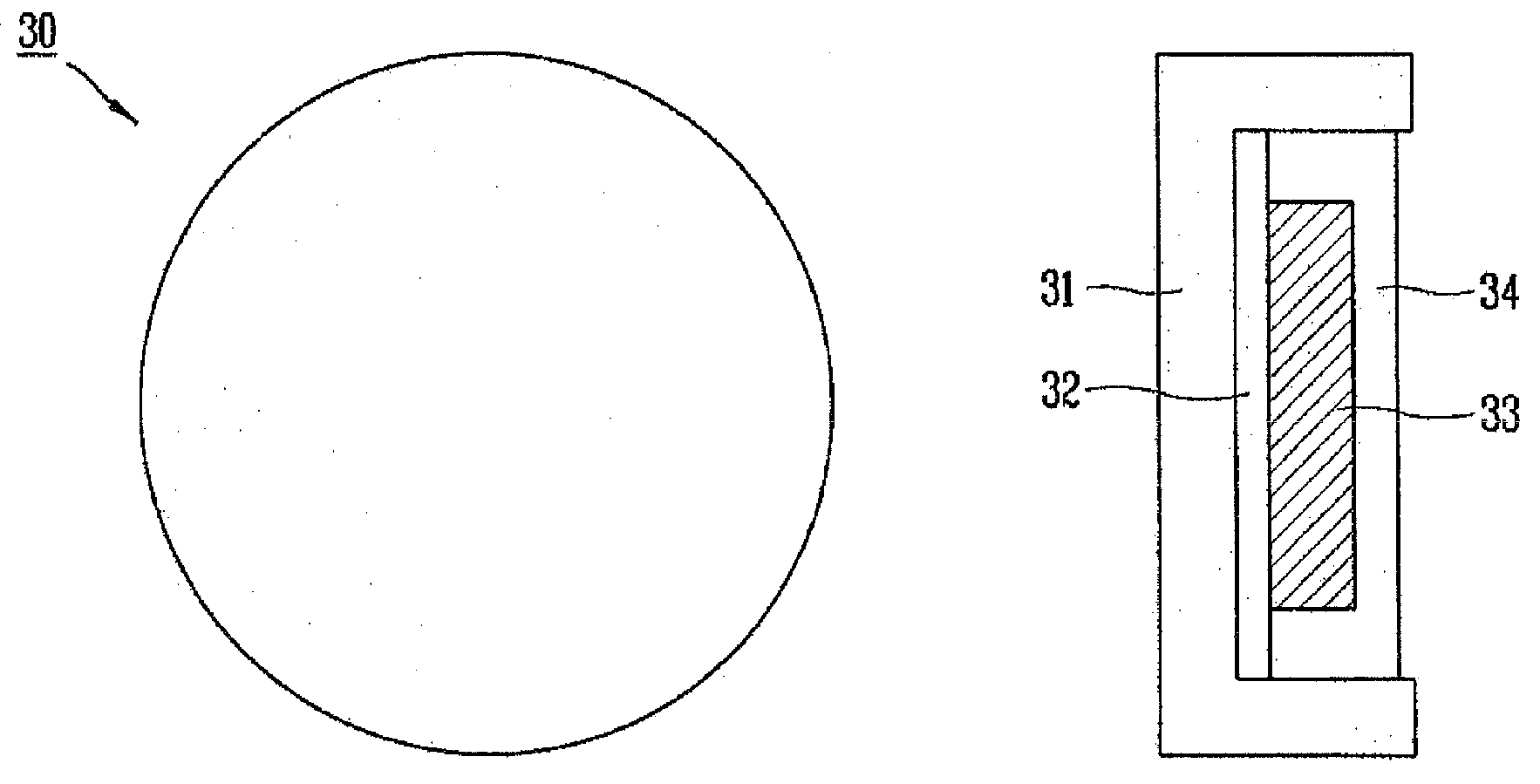
[0065]FIG. 7 is a perspective view illustrating a vacuum insulation panel according to one embodiment of the present invention, FIG. 8 illustrates a getter of FIG. 7, FIG. 9 illustrates another getter of FIG. 7, FIG. 10 is a graph illustrating experimental data of variation by time passage in thermal conductive charact...


PUM

PropertyMeasurementUnit
longitudinal radiusaaaaaaaaaa
temperatureaaaaaaaaaa
porosityaaaaaaaaaa

Abstract

Disclosed are a vacuum insulation panel and an insulation structure of a refrigerator using the same. The vacuum insulation panel comprises a core material formed by gather glass fiber, a getter having a container to receive an absorbent having quicklime of 90 wt % or greater as a main component, and a sealing cover formed to surround the core material and the getter. The core material can be formed at low cost in such a manner that glass fiber is tangled and gathered by penetrating glass wool having glass fiber using a needle. Since the getter is made of quicklime that can first remove water corresponding to a main component of the absorbent, the getter can be manufactured at low cost and has improved insulation efficiency.

Description

TECHNICAL FIELD[0001]The present invention relates to a vacuum insulation panel, and more particularly, to a vacuum insulation panel, a method for manufacturing the same, and an insulation structure of a refrigerator using the same, in which a getter is manufactured at low cost and has improved insulation efficiency by first removing water between gas and water permeated into the vacuum insulation panel, and a core material is manufactured at low cost by gathering glass fiber.BACKGROUND ART[0002]As shown in FIG. 1, a refrigerator 1 is an apparatus for storing food at low temperature, and includes a cabinet 10 constituting a receiving space 20 for receiving food, such as a refrigerating chamber and a freezing chamber, a door (not shown) opening and closing the refrigerating chamber and the freezing chamber, and a mechanical portion (not shown) constituting a refrigerant cycle and maintaining the received food at low temperature.[0003]The cabinet 10 is provided with an insulation mate...

Claims


Application Information

Patent Timeline
Patent Type & Authority Applications(United States)
IPC IPC(8): B32B1/04A47F3/04
CPCB32B3/04Y10T428/231B32B5/10B32B17/02B32B19/00B32B19/045B32B19/06B32B27/12B32B27/34B32B2262/101B32B2307/7242B32B2307/728B32B2509/10F25D23/062F25D2201/14B32B5/06D04H1/4218D04H1/46
Inventor KIM, KYUNG-DOJUNG, DONG-JUKIM, YOUNG-BAE
Owner LG ELECTRONICS INC
Why Eureka
Try Eureka