Microfluidic Analysis System

a microfluidic analysis and microfluidic technology, applied in the field of microfluidic analysis system, can solve the problems of complex prior systems, laborious tasks, physical and control terms,

Inactive Publication Date: 2008-11-13
STOKES BIO LTD
View PDF28 Cites 85 Cited by
  • Summary
  • Abstract
  • Description
  • Claims
  • Application Information

AI Technical Summary

Benefits of technology

[0005]According to the invention, there is provided a microfluidic analysis system comprising a thermal cycling device, the device having a plurality of fixed thermal zones and a fixed conduit passing through the thermal zones, a controller for maintaining each thermal zone

Problems solved by technology

This, however, involves the laborious task of loading the samples and preparing a fresh assa

Method used


Image

  • Microfluidic Analysis System
  • Microfluidic Analysis System
  • Microfluidic Analysis System

Examples


case 1

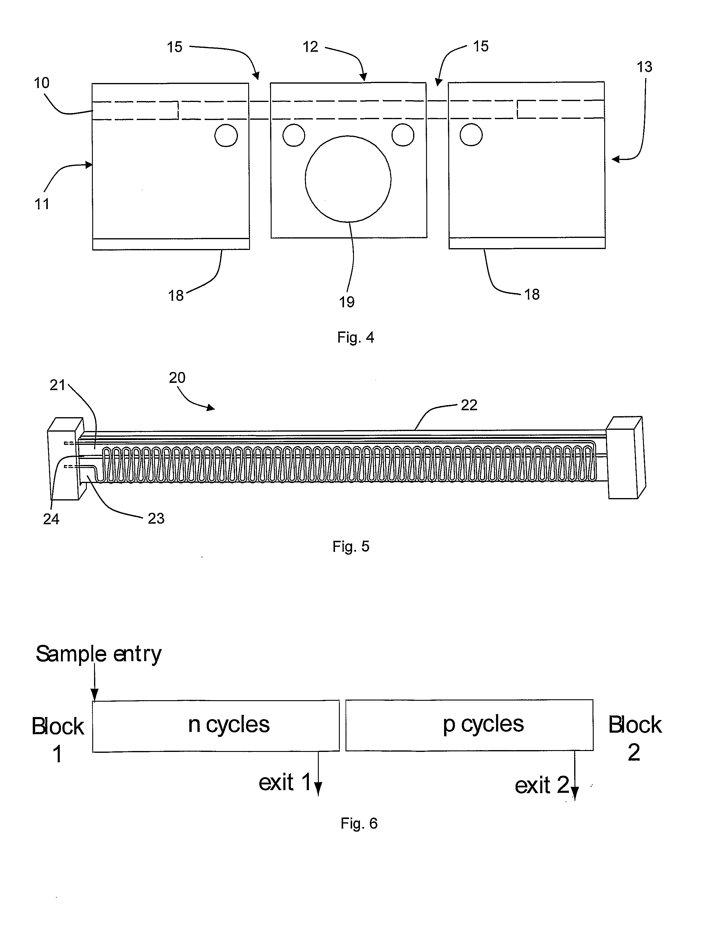
[0065]For a larger cycle number, or an optional extension to the cycle number, the device may be divided into two sections; one with n cycles and one with p cycles as shown in FIG. 6. The combination of the two devices enables a PCR total cycle number of n, p or (n+p) depending on the tubing configuration and the heater control. Each block may be separately controlled to allow for individual use or combined use. Therefore, the cycle number of the device may be varied for greater versatility.[0066]Case 1: Block 2 is thermally controlled and block 1 is uncontrolled (no temperature input). The sample may then enter block 1, flow through the device and exit the thermal cycler at exit 2 following p cycles.[0067]Case 2: The two blocks are thermally controlled. Then the sample enters block 1, flows through the device and exits at exit 2 after (n+p) cycles.[0068]Case 3: The tubing is changed to use exit 1. The sample enters block 1, flows through block 1 and then exits at exit 1 following n...


PUM

PropertyMeasurementUnit
Diameteraaaaaaaaaa
Lengthaaaaaaaaaa
Lengthaaaaaaaaaa

Abstract

A thermal cycling device (3) device a number of fixed thermal zones (11, 12, 13) and a fixed conduit (10) passing through the thermal zones. A controller maintains each thermal zone including its section of conduit (10) at a constant temperature. A series of droplets flows through the conduit (10) so that each droplet is thermally cycled, and a detection system detects fluorescence from droplets at all of the thermal cycles. The conduit is in a single plane, and so a number of thermal cycling devices may be arranged together to achieve parallelism. The flow conduit comprises a channel (17) and a capillary tube (10) inserted into the channel. The detection system may perform scans along a direction to detect radiation from a plurality of cycles in a pass.

Description

FIELD OF THE INVENTION [0001]The invention relates to analysis of samples to which thermal cycling is applied for nucleic acid amplification, such as in the quantitative polymerase chain reaction (qPCR).PRIOR ART DISCUSSION [0002]Conventionally, nucleic acid amplification has involved providing an array of samples in an assay plate and thermally cycling the plate reaction vessel. This, however, involves the laborious task of loading the samples and preparing a fresh assay well plate. It is known to provide a thermal cycler for nucleic acid amplification, and U.S. Pat. No. 5,270,183, WO2005 / 075683, U.S. Pat. No. 6,033,880, and U.S. Pat. No. 6,814,934 describe thermal cycler analysis systems.[0003]The prior systems suffer from being complex, both in physical and control terms. For example, in the system of U.S. Pat. No. 6,033,880 it is necessary to rotate heat exchangers into desired positions, and in the system of U.S. Pat. No. 6,814,934 it is necessary to heat and cool a reaction ve...

Claims


Application Information

Patent Timeline
IPC IPC(8): C12P19/34C12M1/02
CPCB01L3/5027B01L7/525B01L2200/0673B01L2300/0654B01L2300/0838B01L2300/0867B01L2300/1822B01L2300/185B01L2400/0487G01N21/6428G01N2201/0826G01N2201/0833B01L3/502715B01L3/502784B01L2300/0627B01L2300/18C12Q1/686
Inventor DAVIES, MARKDALTON, TARA
Owner STOKES BIO LTD
Why Eureka
Try Eureka