Energy Trigger

a technology of energy trigger and breathing gas, which is applied in the field of measuring and controlling the administration of breathing gas into humans, can solve the problems of pharmacologic therapy that has in general proved disappointing in treating certain breathing disorders, and the risk of breathing disorders to be cured

Active Publication Date: 2008-11-20
BREAS MEDICAL
View PDF9 Cites 46 Cited by
  • Summary
  • Abstract
  • Description
  • Claims
  • Application Information

AI Technical Summary

Benefits of technology

[0022]responding to the reached trigger level by changing control signals for the mechanical ventilator, the control signals controls the supply of breathing gas.

Problems solved by technology

Surgical techniques to remedy breathing disorders constitute a considerable risk for the patient and can lead to permanent injury or even mortality.
Pharmacologic therapy has in general proved disappointing with respect to treating certain breathing disorders, e.g. sleep apnea.
Ventilatory failure includes all forms of insufficient ventilation with respect to metabolic need whether occurring during wake or periods of sleep.
Ventilatory failure is a potentially life threatening condition.
The general comorbidity in patients with failing ventilation is considerable.
The condition is highly disabling in terms of reduced physical capacity, cognitive dysfunction in severe cases and poor quality of life.
Patients with ventilatory failure therefore experience significant daytime symptoms but in addition, the majority of these cases experience a general worsening of their condition during state changes such as sleep.
Daytime complications include sleepiness and cognitive dysfunction.
Not only may CPAP be uncomfortable for the patient due to a sensed increased work of breathing during ventilation, specifically expiration.
Some forms of apnea, mainly including those of central origin, and most forms of hypoventilation are only poorly controlled by CPAP.
A system that does not comply with patient efforts, creates an air trapping situation and increase discomfort for the patient as well as considerably increasing the possibility of anxiety for the patient.
These systems however led to that the patient had to make a higher effort due to that the breathing tubing had to be depressurized before the trigger detection could be made, leaving the patient with a high effort level.
One of the major problems in flow sensor mechanisms is that the system has to calculate the actual leakage from mask, mouth, and other leakages in the breathing circuits, that can lead to machine induced inspiratory triggering problems and missed inspiratory trigger.
If this occurs it will result in that the ventilator is not responding to patient inspiratory and expiratory phases correctly and a high discomfort for the patient.

Method used


Image

  • Energy Trigger
  • Energy Trigger
  • Energy Trigger

Examples


Embodiment Construction

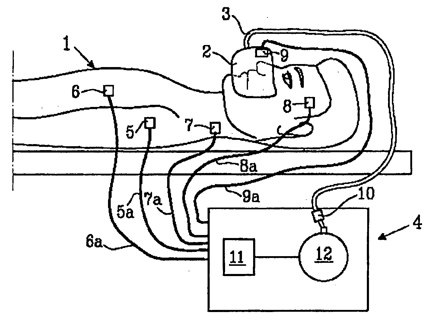
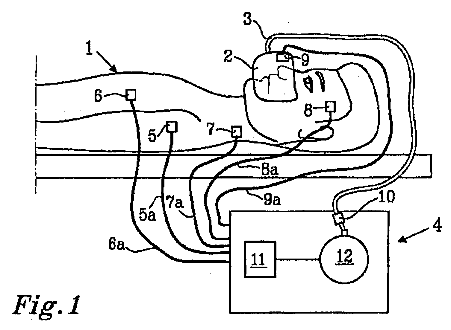
[0040]In FIG. 1 a schematic mechanical ventilation system used for the treatment of hypoventilation disorders is depicted. A ventilation system comprise a mechanical ventilator 4 supplying pressurized breathing gas, tubing 3 for guiding breathing gas to the patient 1, a breathing mask 2 or similar for administrating the breathing gas to the patient 1, sensing means 5, 6, 7, 8, 9 and 10 for determining the physiological status of the patient 1. The number of sensors connected to the mechanical ventilator may be one or more; however, in a preferred embodiment of the present invention at least one sensor is necessary: a breathing gas flow measurement which may be located essentially anywhere along the breathing gas tubing or In the mask. A mechanical ventilator4 is supplying breathing gas for instance as a positive airway pressure via a tubing 3 and through a mask 2 to a patient 1. The mask 2 can be a face mask 2 covering both the mouth and nose or a nasal mask covering only the nose o...


PUM


Abstract

A method and apparatus for facilitating breathing using a mechanical breathing gas ventilator is presented. The patient effort is deduced from a measured flow signal and analyzed with respect to the energy in the breathing system comprising the mechanical ventilator and the patient. When a predetermined energy threshold has been reached the ventilator responds to the breathing pattern change.

Description

FIELD OF THE INVENTION[0001]The present invention relates to the measurement and control of breathing gas administration into humans, and more specifically, the invention relates to a system for rapid response to changes of patient effort during ventilation of breathing gas.BACKGROUND OF THE INVENTION[0002]Patients suffering from different forms of breathing disorders can be subject to several types of treatments depending on the illness or disorder present. Such treatments include surgical procedures, pharmacologic therapy, and non-invasive mechanical techniques. Surgical techniques to remedy breathing disorders constitute a considerable risk for the patient and can lead to permanent injury or even mortality. Pharmacologic therapy has in general proved disappointing with respect to treating certain breathing disorders, e.g. sleep apnea. It Is therefore of Interest to find other treatments, preferably non-invasive techniques.[0003]A mechanical ventilator represents a non-invasive te...

Claims


Application Information

Patent Timeline
Patent Type & Authority Applications(United States)
IPC IPC(8): A61M16/00A61B5/087
CPCA61M16/0051A61M16/0069A61M2016/0036A61M2205/3375A61M2205/3561A61M2205/50A61M2230/04A61M2230/10A61M2230/18A61M2230/205A61M2230/30A61M2230/432A61M2230/435A61M2230/50A61M2230/60A61M2016/0027A61M16/024
Inventor TIEDJE, MIKAEL
Owner BREAS MEDICAL
Why Eureka
Try Eureka