External Fuel Vapor Emission Adjusting Device for Fuel Tank

Inactive Publication Date: 2008-11-20
SENTEC E&E CO LTD
View PDF10 Cites 25 Cited by
  • Summary
  • Abstract
  • Description
  • Claims
  • Application Information

AI Technical Summary

Benefits of technology

[0007]The fuel vapor emission adjusting device utilizes the oil spill trip valve, the at least two fuel vapor filtering passages connecting in series to improve the filter capacity for filtering the hazardous substance, and further utilizes the oil spill trip valve, the at least two

Problems solved by technology

However, only one canister is generally provided, the filter capacity of the canister is limited by the quantity of the trap valve and activated carbon.
In addition, the fuel vapor recycling is also limited by the quantity of the trap valve and activated carbon, i.e. the quan

Method used


Image

  • External Fuel Vapor Emission Adjusting Device for Fuel Tank
  • External Fuel Vapor Emission Adjusting Device for Fuel Tank
  • External Fuel Vapor Emission Adjusting Device for Fuel Tank

Examples


Embodiment Construction

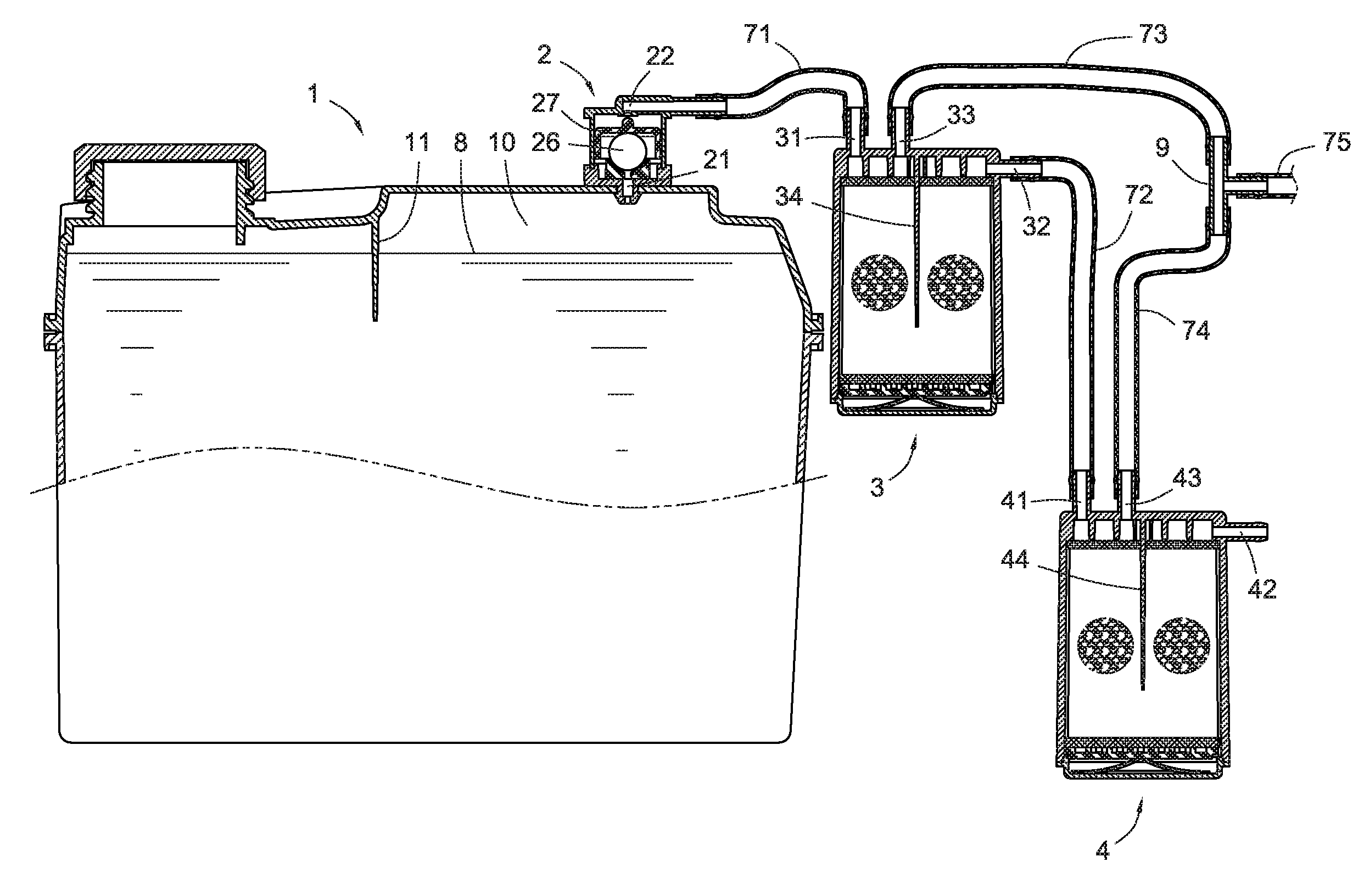
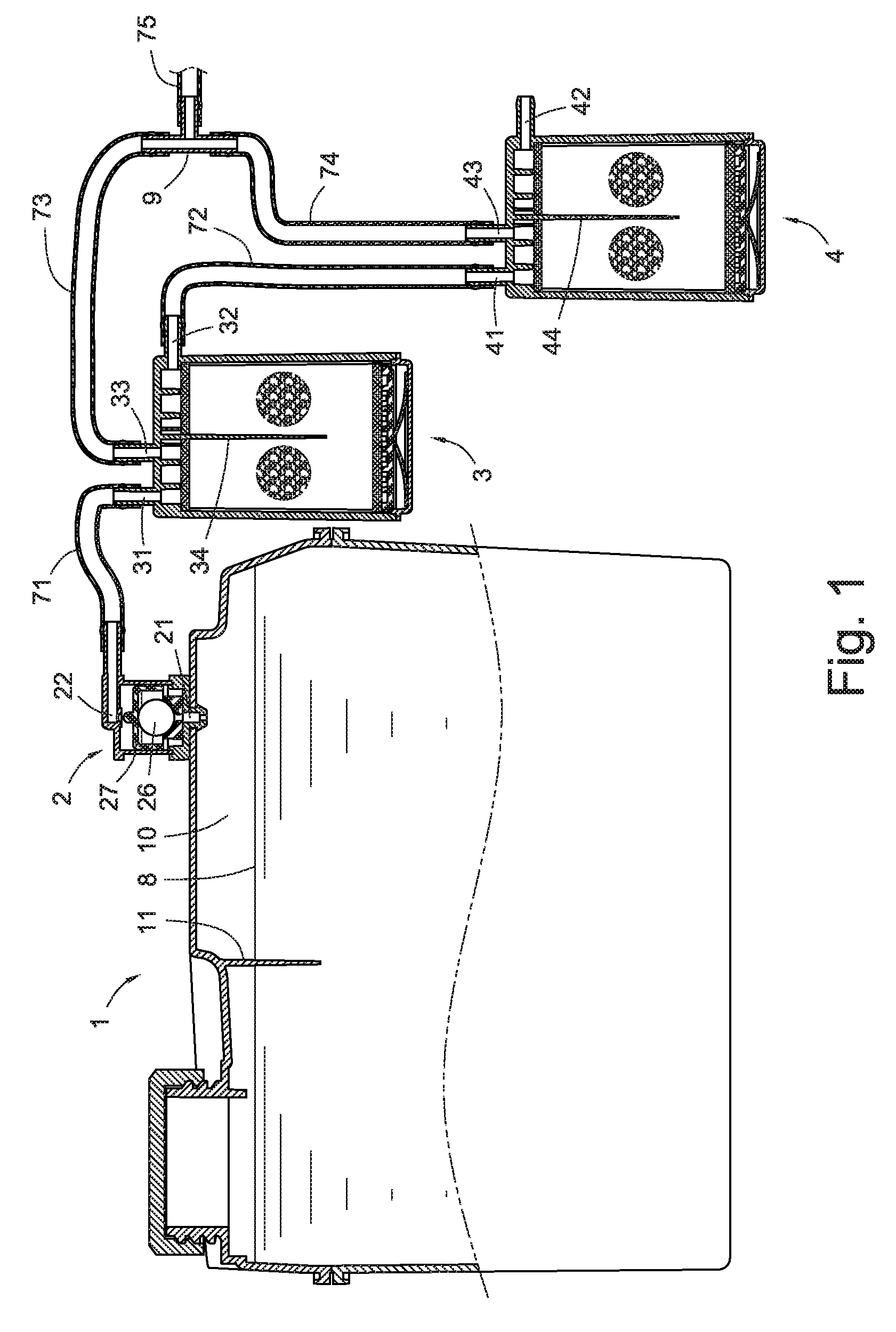
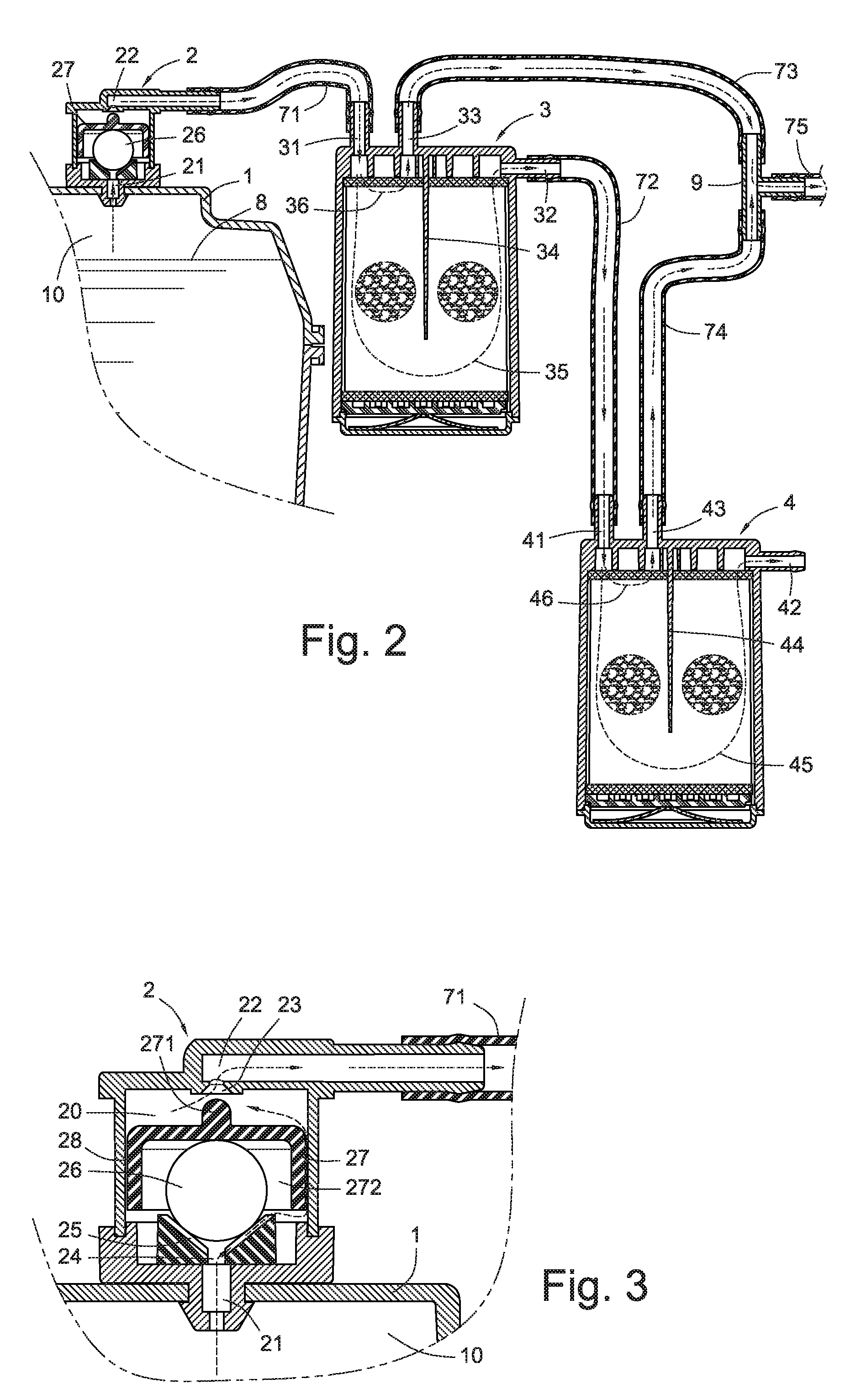
[0028]Referring to FIGS. 1-3, a fuel vapor emission adjusting device according to a first embodiment of the present invention is shown. The fuel vapor emission adjusting device has a clapboard 11 formed in a top portion of a fuel tank 1, which is used to space a top surface of the fuel received therein to form an expansion chamber 10 for concentrating fuel vapor therein. The fuel vapor emission adjusting device further has an oil spill trip valve 2 at a top portion of the fuel tank 1, connecting with the expansion chamber 10, and two canisters 3, 4 disposed at an outside of the fuel tank 1.

[0029]The oil spill trip valve 2 includes a valve chamber 20, a leading-in vent 21, an educing vent 22 (as shown in FIG. 3). The leading-in vent 21 and the educing vent 22 respectively connects with the valve chamber 20, and another end of the leading-in vent 21 is connected to the expansion chamber 10. The educing vent 22 protrudes toward the valve chamber 20 to form a pyramidal opening 23 at the...


PUM


Abstract

A fuel vapor adjusting device includes an expansion chamber at a top portion of a fuel tank; an oil spill trip valve being connected to the expansion chamber, which can turn off when there's spilling oil or the fuel tank is fell down; and at least two canisters. Each canister includes a fuel vapor entrance port, a fuel vapor outlet port, and a fuel vapor recycling vent. The fuel vapor entrance port and the fuel vapor outlet port form a fuel vapor filtering passage, and the fuel vapor entrance port and the fuel vapor recycling vent form a fuel vapor recycling passage. The oil spill trip valve, the at least two fuel vapor filtering passages connect in series, and the oil spill trip valve, the at least two fuel vapor recycling passages connect in parallel.

Description

BACKGROUND[0001]The present invention relates to a fuel tank, particular relates to an external fuel vapor emission adjusting device for adjusting the pressure of fuel vapor therein and stopping overflowing of fuel.[0002]In the conventional technology, for avoiding the leaking of the fuel vapor in the fuel tank, a canister is applied at the passage connected with the atmosphere environment. The canister has a plurality of trap valves (filter) and activated carbons for trapping the hazardous substance in the fuel vapor and avoiding discharging it into the atmosphere and avoiding contaminating the atmosphere.[0003]In addition, except that the fuel in the fuel tank is applied to the engine, the fuel vapor is also stored and purged to an engine air inlet connected to a recycling vent of the canister upon an intermittent negative pressure produced when the engine operates.[0004]However, only one canister is generally provided, the filter capacity of the canister is limited by the quantit...

Claims


Application Information

Patent Timeline
IPC IPC(8): F28B9/00
CPCB60K15/03519B60K2015/03514F02M25/0836F02M25/089F16K24/04Y10T137/5835
Inventor WANG, AARONHUANG, CHUN-CHAO
Owner SENTEC E&E CO LTD
Why Eureka
Try Eureka