Single-stage hypersonic vehicle featuring advanced swirl combustion

a single-stage, hypersonic technology, applied in the direction of machines/engines, aircraft navigation control, composite engine plants, etc., can solve the problems of reducing vehicle thrust, costing most missions, and being less competitive in the world launch market, so as to reduce length, weight, cooling requirements and complexity, and reduce propulsion and launch costs. , the effect of reducing the number of times

Inactive Publication Date: 2008-11-20
UNITED TECH CORP
View PDF62 Cites 45 Cited by
  • Summary
  • Abstract
  • Description
  • Claims
  • Application Information

AI Technical Summary

Benefits of technology

[0011]A single-stage hypersonic vehicle is comprised of a low-speed propulsion system and a high-speed propulsion system. The low-speed propulsion system propels the single-stage vehicle to a threshold velocity, at which the high speed propulsion system then takes over. The low-speed propulsion system includes a combined-cycle engine featuring a swirl generator, which is based on advanced swirl combustion technology, and then integrated into a turbojet engine to provide a compact turbojet and swirl afterburner-ramjet propulsion system. The high-speed propulsion system includes a hypersonic engine that is operable at the threshold takeover velocity and beyond. In various embodiments, the high-speed propulsion system comprises a scramjet, rocket, or scramjet / rocket engine depending on the mission profile and requirements. Benefits of the swirl generator design include its ability to significantly reduce length, weight, cooling requirements and complexity for the low-speed and high-speed propulsion systems, while maintaining high propulsion performance and reducing propulsion and launch costs.

Problems solved by technology

However, most of the existing rocket designs are expendable, making them costly for most missions and less competitive in the world launch market.
Above this limit the combustion chamber temperature becomes very high, causing the combustion products to dissociate, which in turn reduces vehicle thrust.
This creates synergy since the ramjet can utilize the isolator that is already required by the turbine engine in a typical turbine based combined cycle concept installation, rather than creating a second isolator in the high speed flowpath.

Method used


Image

  • Single-stage hypersonic vehicle featuring advanced swirl combustion
  • Single-stage hypersonic vehicle featuring advanced swirl combustion
  • Single-stage hypersonic vehicle featuring advanced swirl combustion

Examples


Embodiment Construction

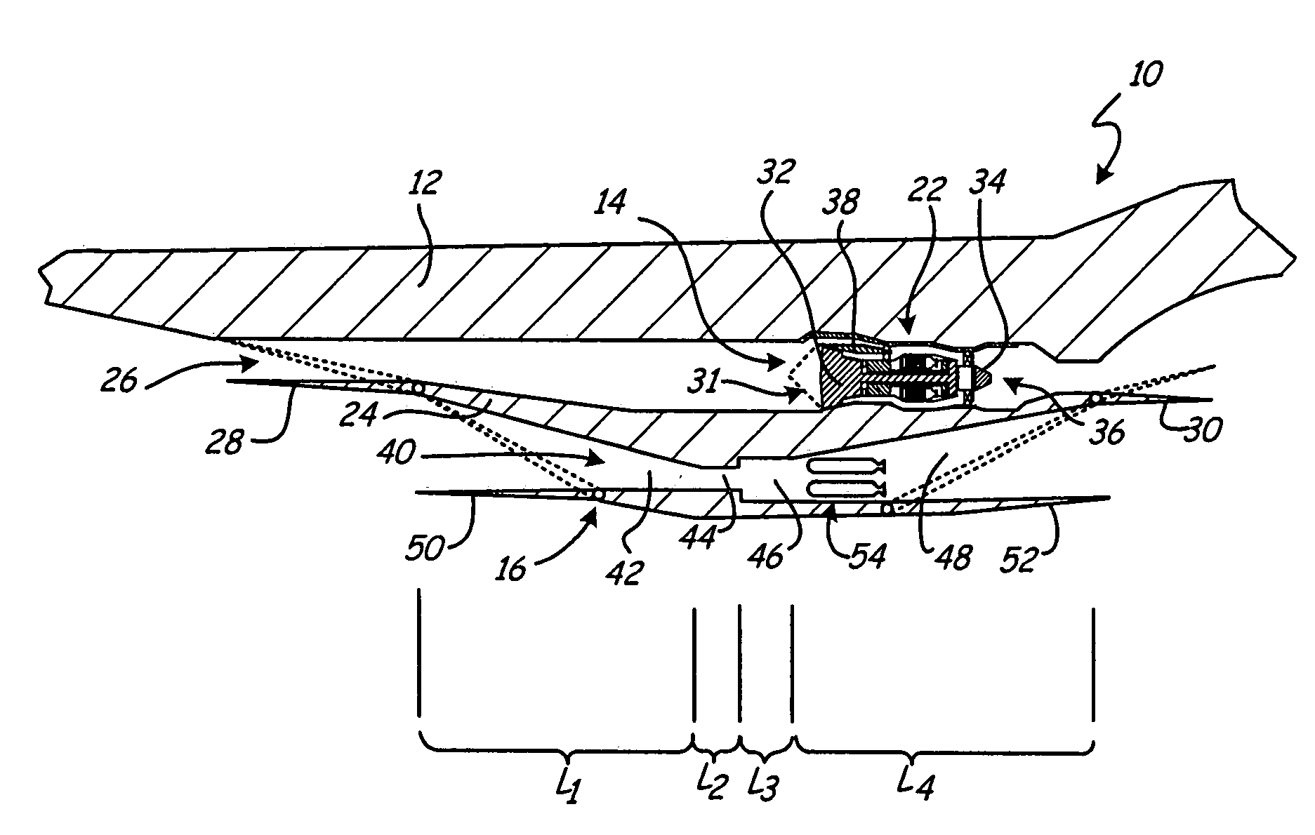
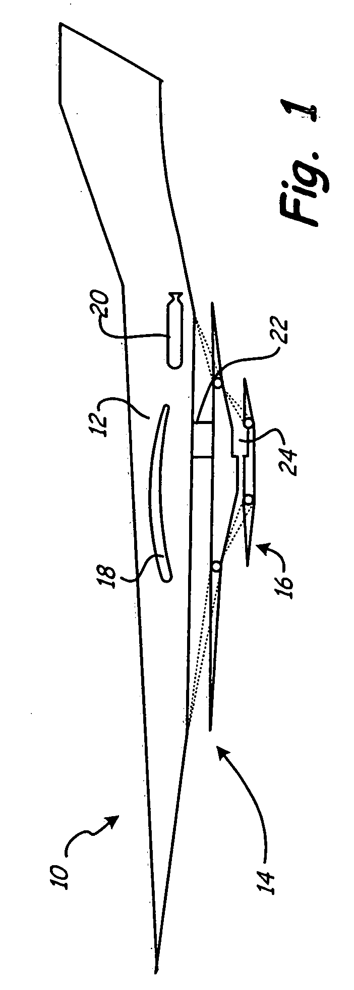
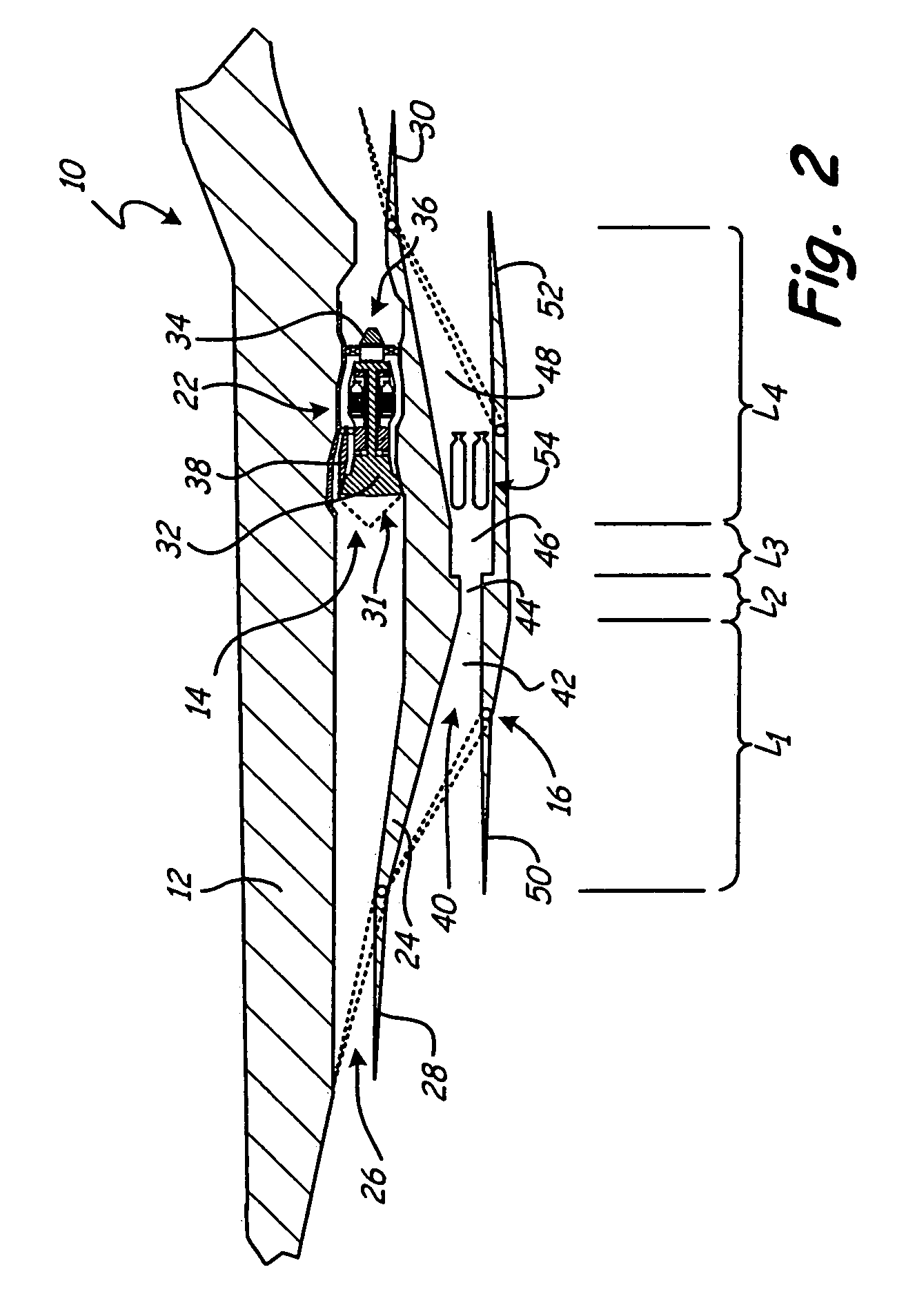
[0017]FIG. 1 shows a diagram of single-stage vehicle 10 of the present invention. Single-stage vehicle 10 includes fuselage 12, in which low-speed propulsion system 14 and high-speed propulsion system 16 are incorporated. Fuselage 12 includes a pair of airfoils, including airfoil 18, and is configured for achieving flight by low-speed propulsion system 14 up to approximately a flight speed of Mach 6. At such a scramjet takeover speed, high-speed propulsion system 16 would continue to accelerate the single-stage vehicle to a Mach number range of approximately 10 to 18, depending on the mission requirements (e.g., high altitude global strike / reconnaissance). The scramjet takeover speed is typically a speed at which hypersonic propulsion becomes viable and is also known as a hypersonic threshold speed. Single-stage vehicle 10 also includes other components required for controlling and propelling vehicle 10, such as flight control systems and fuel systems, which are not shown for clarit...


PUM


Abstract

A single-stage hypersonic vehicle is comprised of a low-speed and a high-speed propulsion system. The low-speed propulsion system propels the single-stage vehicle to a threshold velocity, after which the high-speed propulsion system then takes over. The low-speed propulsion system includes a combined-cycle engine featuring a swirl generator that is integrated into a turbojet engine to provide a compact turbojet and swirl afterburner-ramjet propulsion system. The high-speed propulsion system includes a hypersonic engine that is operable at the threshold takeover velocity and beyond. In various embodiments, the high-speed propulsion system comprises a scramjet, rocket, or scramjet/rocket engine depending requirements. Benefits of the swirl generator design include its ability to rapidly and efficiently atomize, vaporize, mix and burn the fuel and oxidizer for the low speed propulsion system, significantly reduce length, weight, cooling requirements and complexity for both propulsion systems, while maintaining high propulsion performance and reducing propulsion and launch costs.

Description

CROSS-REFERENCE TO RELATED APPLICATION(S)[0001]The present application is related to the following copending application filed on the same day as this application: “TWO-STAGE HYPERSONIC VEHICLE FEATURING ADVANCED SWIRL COMBUSTION by inventors Robert J. Pederson, Stephen N. Schmotolocha and William W. Follett (attorney docket number U73.12-088), which is incorporated herein by this reference.BACKGROUND OF THE INVENTION[0002]This invention relates generally to single-stage hypersonic vehicles and more particularly to propulsion systems for single-stage vehicles. Hypersonic vehicles are generally characterized as capable of achieving speeds of greater than approximately Mach 5, and have typically relied on rocket engines to achieve such speeds.[0003]Launch vehicles or rocket boosters are primarily used to deliver satellites to orbit or weapons over large distances (ICBMs). However, most of the existing rocket designs are expendable, making them costly for most missions and less competi...

Claims


Application Information

Patent Timeline
Patent Type & Authority Applications(United States)
IPC IPC(8): B64C30/00F02K7/14F02K3/00
CPCB64C30/00B64D33/02B64D33/04B64D2033/026F02K7/14F02K7/16F02K7/18Y02T50/671Y02T50/60
Inventor PEDERSON, ROBERT J.SCHMOTOLOCHA, STEPHEN N.FOLLETT, WILLIAM W.
Owner UNITED TECH CORP
Why Eureka
Try Eureka