Gas spring assembly

a technology of gas springs and springs, which is applied in the direction of shock absorbers, mechanical devices, transportation and packaging, etc., can solve the problems of reduced resistance to gas flow, less comfort, and minimal damping characteristics, and achieve the effect of dissipating kinetic energy and dissipating kinetic energy

Inactive Publication Date: 2008-11-20
FIRESTONE IND PROD COMPANY
View PDF27 Cites 19 Cited by
  • Summary
  • Abstract
  • Description
  • Claims
  • Application Information

AI Technical Summary

Benefits of technology

[0009]A gas spring assembly in accordance with the present novel concept for an associated vehicle having an associated unsprung mass and an associated sprung mass is provided. The gas spring assembly includes a first end member that is operatively connected to one of the associated sprung mass and the associated unsprung mass, and a second end member that is spaced from the first end member toward the other of the associated sprung mass and the associated unsprung mass. A flexible wall is secured between the first and second end members and at least partially forms a first gas chamber therebetween. A confinement at least partially defines a second gas chamber. A porous flow restrictor is disposed in fluid communication between the first and second gas chambers. The porous flow restrictor defines a plurality of fluid flow passages that are operative to maintain laminar gas flow under relative displacement between the first and second end members of the gas spring, which displacement generates gas flow between the first and second gas chambers through the porous flow restrictor.
[0010]A suspension system in accordance with the present novel concept for an associated vehicle having an associated sprung mass and an associated unsprung mass is provided. The suspension system includes a gas spring assembly that is operatively connected between the associated sprung and unsprung masses. The gas spring assembly includes a first end member, a second end member spaced from the first end member and a flexible wall secured between the first and second end members that at least partially forms a first gas chamber therebetween. A confinement at least partially defines a second gas chamber. A porous flow restrictor is disposed in fluid communication between the first and second gas chambers. The porous flow restrictor defines a plurality of fluid flow passages that are operative to maintain laminar gas flow under relative displacement between the first and second end members of the gas spring, which displacement thereby generates gas flow between the first and second gas chambers through the porous flow restrictor. A pressurized gas source is in fluid communication with one of the first and second gas chambers. A valve assembly is fluidically connected between the pressurized gas source and at least one of the first and second gas chambers. A control system is operative to selectively energize the valve assembly for controlling fluid communication between the pressurized gas source and at least one of the first and second gas chambers.
[0011]A gas spring assembly in accordance with the present novel concept is provided that includes a first end member, a second end member spaced from the first end member and a flexible wall secured between the first and second end members that at least partially forms a first gas chamber therebetween. A confinement at least partially defines a second gas chamber. A porous flow restrictor is disposed in fluid communication between the first and second gas chambers. The first end member, the second end member and the flexible wall together forming a gas spring having a spring rate corresponding to the first gas chamber. The spring rate varies as a function of frequency of vibration and has a first resonant frequency. The second gas chamber and the porous flow restrictor are operative to generate a reduced-spring rate region of performance that is substantially frequency independent through a range of frequencies below the first resonant frequency.
[0012]A gas spring and gas damper assembly in accordance with the present disclosure is provided for use on an associated vehicle having an associated ...

Problems solved by technology

That is, it is well understood in the art that the use of spring elements having higher spring rates (i.e., stiffer springs) will transmit a greater magnitude of road inputs into the sprung mass of the vehicle and that this typically results in a rougher, less-comfortable ride.
Various disadvantages exist with known gas spring constructions that include additional gas volumes to assist in reducing the spring rate of the gas spring, and at least some of these disadvantages involve the movement of air between the two volumes.
However, such pathways would provide reduced resistance to gas flow and, thus, provide minimal damping characteristics.
What's more, such very large pathways are often difficult to provide, given the limited operating and mounting envelopes normally associated with vehicle suspension systems.
However, such alterations would normally provide increased damping performance at the expense of other performance characteristics of the gas spring.
That is, the changes that increase the resistanc...

Method used


Image

  • Gas spring assembly
  • Gas spring assembly
  • Gas spring assembly

Examples


Embodiment Construction

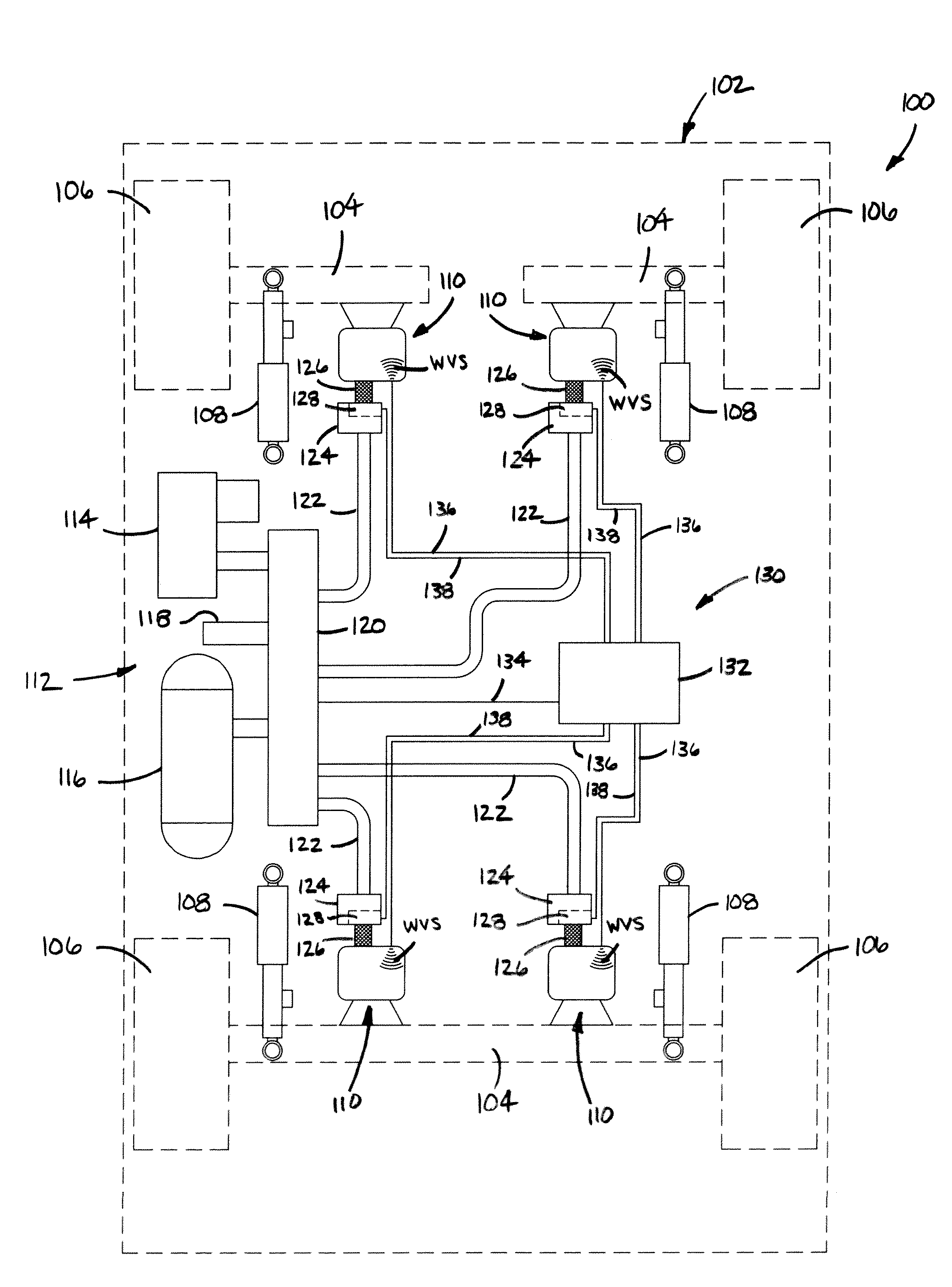
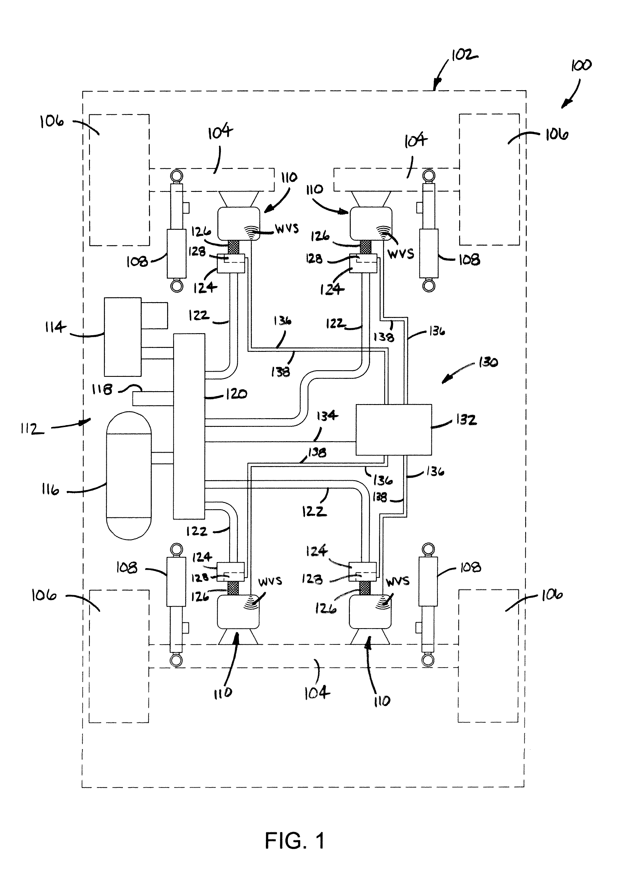
[0019]Turning now to the drawings wherein the showings are for the purpose of illustrating exemplary embodiments of the present novel concept and not for limiting the same, FIG. 1 illustrates a vehicle 100 having a sprung mass, such as a vehicle body 102, for example, and an unsprung mass, such as axles 104 and / or wheels 106, for example. Additionally, plurality of liquid damping members, such as shock absorbers 108, for example, can be secured between the sprung and unsprung masses of the vehicle in a suitable manner. It will be appreciated, however, that such damping members are optionally included in the exemplary embodiment in FIG. 1. Additionally, a plurality of gas spring assemblies 110 (which may also be referred to herein as “gas spring and gas damper assemblies”) are disposed between the sprung and unsprung masses of the vehicle, such as adjacent wheels 106 and shock absorbers 108 as shown in FIG. 1, for example.

[0020]Vehicle 100 also includes a pressurized gas system 112 t...


PUM


Abstract

A gas spring assembly that is suitable for use on a vehicle suspension system includes a first end member and a second end member that is spaced from the first end member. A flexible wall is secured between the first and second end members and at least partially defines a first gas chamber therebetween. A confinement at least partially forms a second gas chamber that is in communication with the first gas chamber. A porous flow restrictor is operatively disposed between the gas chambers. A suspension system including such a gas spring assembly as well as a method is also included.

Description

BACKGROUND[0001]The present disclosure broadly relates to the art of vehicle suspension systems and, more particularly, to a gas spring assembly suitable for use on a vehicle suspension system. The gas spring assembly includes a porous flow restrictor capable of maintaining laminar gas flow between two gas chambers that are interconnected by the porous flow restrictor.[0002]Vehicle suspension systems typically include a plurality of spring elements for accommodating forces and loads associated with the operation and use of the vehicle. In such vehicle suspension system applications, it is often considered desirable to select spring elements that have the lowest suitable spring rate, as this favorably influences ride quality and comfort. That is, it is well understood in the art that the use of spring elements having higher spring rates (i.e., stiffer springs) will transmit a greater magnitude of road inputs into the sprung mass of the vehicle and that this typically results in a rou...

Claims


Application Information

Patent Timeline
IPC IPC(8): F16F9/00
CPCB60G11/27B60G17/04B60G17/0521B60G2202/152B60G2204/111B60G2400/252B60G2400/91B60G2500/20B60G2500/22F16F9/0472
Inventor HAYES, BRADLEY W.MOULIK, PRADIPTA N.KELSEY, SYDNEY
Owner FIRESTONE IND PROD COMPANY
Why Eureka
Try Eureka