Low and reverse pressure application hydrodynamic pressurizing seals

a technology of hydrodynamic pressure and low pressure, applied in the direction of engine seals, mechanical equipment, engine components, etc., can solve the problems of chemical modification of oil, adverse to the performance of the equipment where the seal is used, and affecting the performance of the gas turbin

Inactive Publication Date: 2008-11-20
STEIN SEAL
View PDF8 Cites 28 Cited by
  • Summary
  • Abstract
  • Description
  • Claims
  • Application Information

AI Technical Summary

Benefits of technology

[0008]The present invention relates to an apparatus and method for sealing a liquid sump. More specifically, the present invention relates to circumferential seal ring segments designed to genera...

Problems solved by technology

Leakage of liquids from the lubricant side into the gas side adversely affects performance of the equipment where the seal is used.
In case of an aircraft engine, oil leakage across the seal into a hot air side may cause oil coking or an engine fire.
More specifically, when an oil lubricant is used, mixing the oil with the gas could result in formation of oil coke, a byproduct of oil heated to an elevated t...

Method used


Image

  • Low and reverse pressure application hydrodynamic pressurizing seals
  • Low and reverse pressure application hydrodynamic pressurizing seals
  • Low and reverse pressure application hydrodynamic pressurizing seals

Examples


first embodiment

[0045]The seal ring segments 60 are specifically machined to contain a plurality of grooves along a shaft-side face of the each segment such that these grooves generate high gas pressures across seal rings and the shaft. This increased pressure prevents fluid from leaking within spaces between the shaft 40 and the seal segments 60 during the operation of the shaft 40. In a first embodiment the grooves along the shaft-side face 110 of the seal segments 60 are a dead end circumferential groove 115 and at least one or a plurality hydrodynamic inclined pumping grooves 105. The circumferential dead end groove of each segment extends along the longitudinal axis of the shaft-face of the ring segment 60 such that, when the segments are linked, the dead end circumferential groove extends arcuately in the direction of shaft rotation. Preferably, a bore dam is spaced between the dead end circumferential groove and the lubricant side of the chamber. The width and depth of the grooves 115 and 10...

second embodiment

[0057]In the present invention, referring to FIGS. 9A and B, the additional grooves along the shaft-side face 110 of the seal 60 are formed by at least one hydrodynamic shallow pocket 129, comprised of a pocket 130, inlet 135 and outlet 140, and a dead end circumferential groove 115. Specifically, the pockets 130 may be substantially square shaped, as illustrated. However, the pocket is not limited to this configuration. Rather, the pocket 130 may be rectangular, circular, oval, or any other aerodynamic and / or hydrodynamic configuration understood in the art. Extending from one end of each pocket 130 which is distal to the dead end circumferential groove is an inlet 135 wherein the inlet 135 extends from the pocket 130 such that it is adapted to receive fluid flow from the rotatable shaft, as discussed below. Extending from an opposing end of each pocket 130, which is proximal to the dead end circumferential groove 115, is an outlet 140 wherein the outlet 140 places each pocket 130 ...

third embodiment

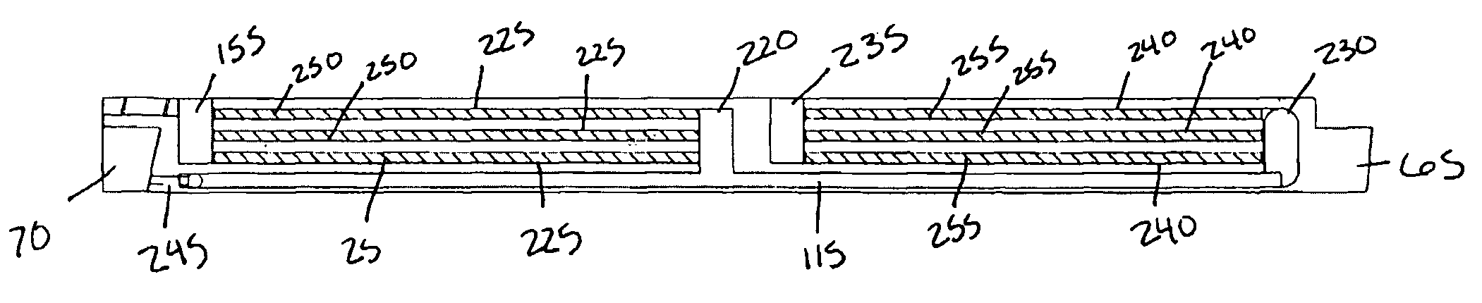
[0065]In the present invention, referring to FIG. 11, the additional grooves along the shaft-side face of the seal 60 is at least one axial bore groove 155, which extends perpendicularly to the longitudinal axis of the seal segment, and a dead end circumferential groove 115. The axial bore groove 155 is desirably on one end of the seal segment 60 that is proximal to the segment's tongue 65. However, the present invention is not limited to this embodiment. The axial bore groove 155 may be substantially square or rounded with a depth within the range of 0.0005 to 0.035 inches wherein the depth is desirably between 0.20 to 0.025 inches in depth. The depth of the axial bore groove 155 may be dependent upon multiple factors including, but not limited to, the engine application, shaft rotational speeds, desired seal life and the like. The axial bore may also be aerodynamically or hydrodynamically tapered such that air flow generated by the rotation of the shaft is received by the axial bo...


PUM


Abstract

The present invention relates to circumferential seal ring segments positioned around a rotating shaft so as to prevent fluids from leaking from a lubricant sump during both low and high pressure conditions. The circumferential seal is comprised of a plurality of adjoining annular ring segments facing the rotating shaft. Each sealing ring segment includes a dead end circumferential groove on a shaft-side face of each sealing ring such that, when the segments are joined, the circumferential dead end groove of each segment extends arcuately in the direction of shaft rotation. At least one additional groove is contained on the shaft-side face of each sealing ring segment. The additional groove(s) directs and creates pressurized air within the dead end circumferential groove, either directly or indirectly maintaining a seal between the ring segments and the shaft. A bleed hole may also be provided to create a seal between each sealing segment.

Description

CROSS REFERENCE TO RELATED PATENT APPLICATION[0001]This patent application is a continuation-in-part of U.S. patent application Ser. No. 11 / 821,578, filed on Jun. 21, 2007, which claims priority from Provisional U.S. Patent Application Ser. No. 60 / 815,782, filed Jun. 21, 2006, in the names of Thurai Maanik Vasagar, Alan D. MeNieckle (now deceased), and Glenn Marke Garrison, and assigned to Stein Seal Company.FIELD OF THE INVENTION[0002]The present invention relates to an apparatus and method for sealing a liquid sump. More specifically, the present invention relates to seal ring segments designed to generate high gas pressures across the seal and around a rotating shaft so as to prevent liquids from leaking from a liquid side of the seal to a gas side of the seal during low and high pressure conditions.BACKGROUND OF THE INVENTION[0003]There are many applications wherein housings are provided with a plurality of interior sections having rotating parts passing therethrough, wherein on...

Claims


Application Information

Patent Timeline
IPC IPC(8): F16J15/34
CPCF16J15/3244F16J15/441F16J15/40
Inventor VASAGAR, THURAI MANIKMCNICKLE, ALAN D.MCNICKLE, DIANE R.GARRISON, GLENN M.
Owner STEIN SEAL
Why Eureka
Try Eureka