Prelubricated Multi-Lipped Radial Shaft Seal With Large Radial Offset Accommodation

a radial shaft and accommodation technology, applied in the field of radial shaft seals, can solve the problems of not providing lubricating or cooling function, and achieve the effect of convenient carrying and excellent sealing efficiency

Inactive Publication Date: 2008-11-20
FREUDENBERG NOK GEN PARTNERSHIP
View PDF35 Cites 37 Cited by
  • Summary
  • Abstract
  • Description
  • Claims
  • Application Information

AI Technical Summary

Benefits of technology

[0004]The radial shaft seal of the present disclosure provides an annular outer rigid insert adapted to reinforce an elastomeric rind portion surrounding and extending axially along the tubular portion of the outer rigid insert to effect a sealing press-fit into the interior of a housing bore. The elastomeric rind portion terminates and wraps inward around an inward radiating wall end portion of the outer rigid insert where the elastomer forms into a flex portion that extends axially, which is radially spaced from the tubular portion of the outer rigid insert. This flex portion terminates and is attached to an elastomeric bearing portion of the seal. The elastomer flows axially along and around the outside of an inner rigid insert where it joins with the elastomer of the reinforced bearing portion and forms a pair of flexible seal lips that hug and seal around the shaft, the sealing action of a first seal lip is intensified and assured by a garter spring mounted around the flexible seal lip while a second seal lip, along with the first seal lip, defines an enclosed lubrication chamber. The lubrication chamber contains lubrication for the seal lips and bearing portion.
[0005]The reinforced elastomeric bearing portion includes a plurality of raised ribs the innermost bearing surfaces of which lie tangentially to the shaft surface and which have either a flat or slightly convex shape but which includes rounded edges at the intersection of the sides of the raised ribs and the bearing surfaces. The bearing surfaces of the ribs form an acute angle with the surface of the shaft which facilitates the carrying of liquid fed from the grooves between the ribs and which forces the fluid into the acute angles thus wedging the fluid between the reinforced elastomeric bearing interior surfaces and the shaft exterior creating a full film elastohydrodynamic lubrication regime between the reinforced bearing interior and the shaft exterior. The reinforced bearing portion being attached to the adjacent flexible seal lips causes the bearing and seal lip portions to be held circular and concentric, and to track true to the shaft being sealed regardless of considerable shaft to bore misalignment, offset and dynamic run out, thus assuring excellent sealing efficiency.

Problems solved by technology

One problem with radial shaft seals is that shaft offset or other misalignment and / or dynamic run out conditions relative to the housing bore can cause the seal lip to be unable to follow and thus lift off the shaft, allowing fluid to escape and leak past the seal.
However, during some periods of operation, such as the spin cycle of a washing machine, the fluid (water) may be missing from the seal environment and therefore, does not provide the lubricating or cooling function.

Method used


Image

  • Prelubricated Multi-Lipped Radial Shaft Seal With Large Radial Offset Accommodation
  • Prelubricated Multi-Lipped Radial Shaft Seal With Large Radial Offset Accommodation
  • Prelubricated Multi-Lipped Radial Shaft Seal With Large Radial Offset Accommodation

Examples


Embodiment Construction

[0014]The following description is merely exemplary in nature and is not intended to limit the present disclosure, application, or uses.

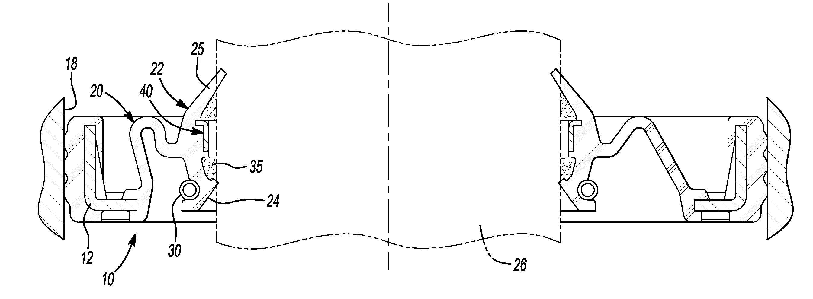
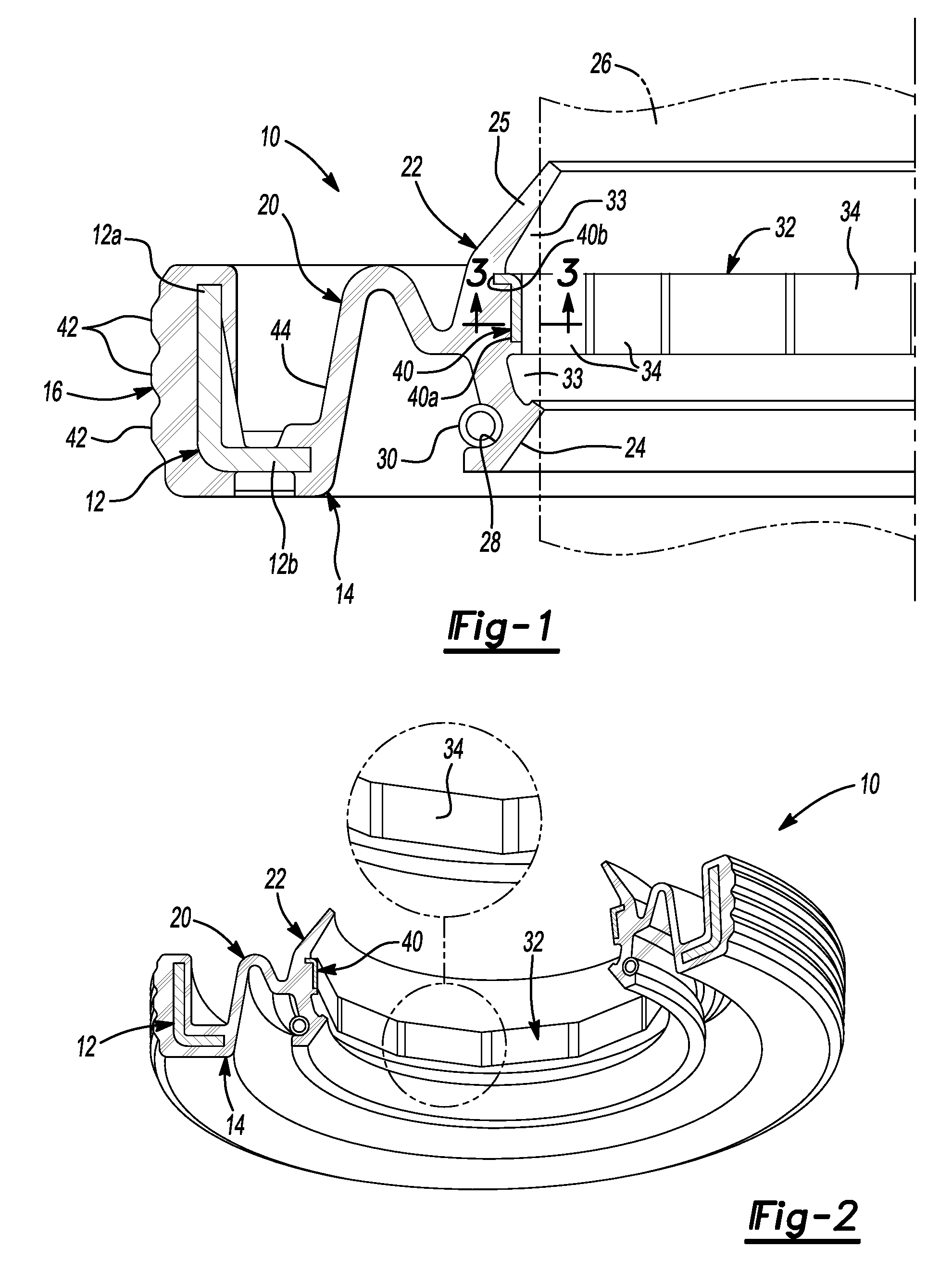
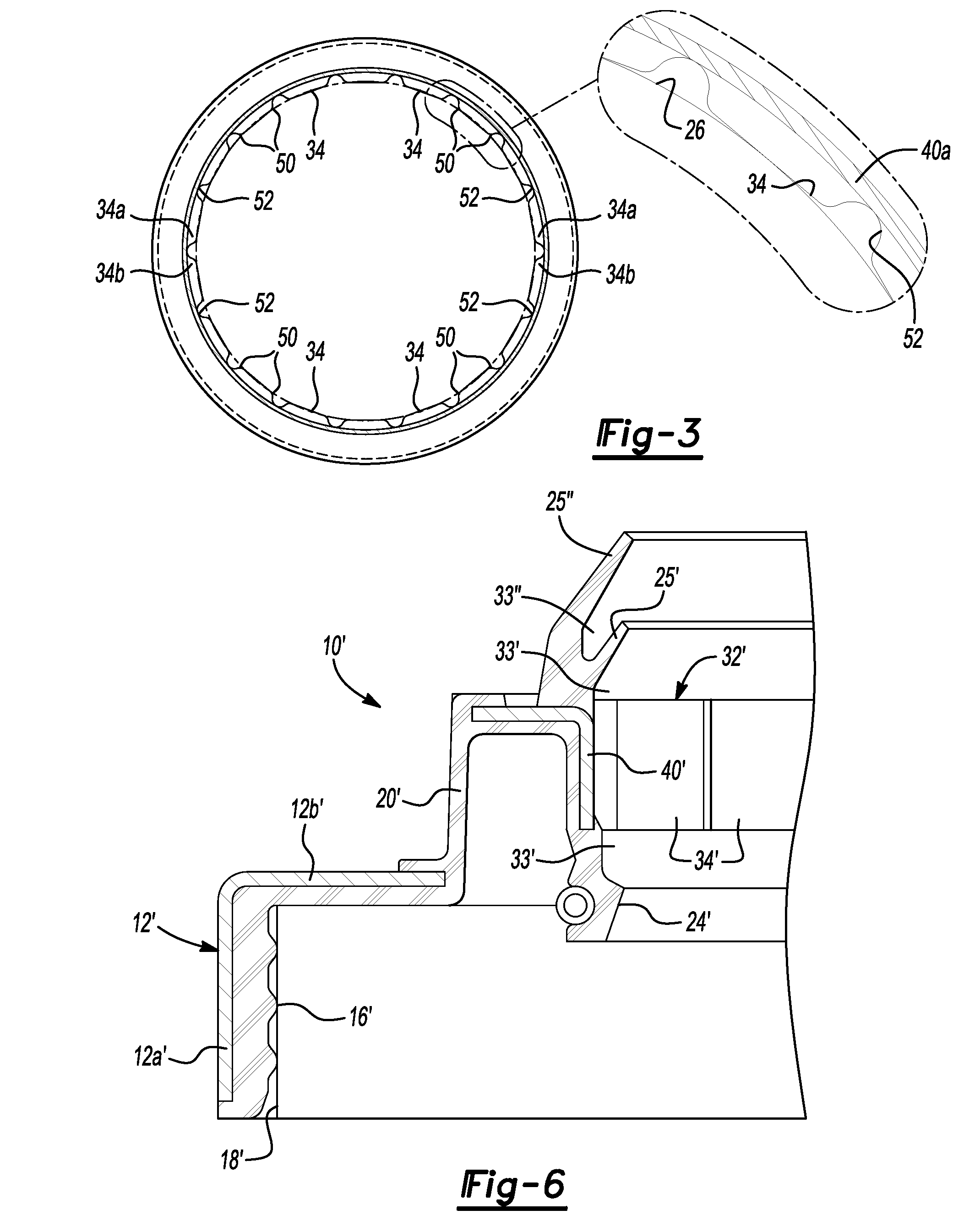
[0015]With reference to FIGS. 1-5, a radial shaft seal 10 according to the principles of the present disclosure will now be described. As shown in FIG. 1, the radial shaft seal 10 includes an annular retainer insert 12 having an annular elastomeric seal body 14 molded to the retainer insert 12. The seal body includes an over-molded portion 16 molded to the retainer insert 12 while providing a sealed connection with a housing 18 as best illustrated in FIGS. 4 and 5.

[0016]A flexible thin walled flex section portion 20 extends axially from an inner surface of the retainer insert 12. A seal portion 22 extends radially inward from a radially inward end of the flex section portion 20 and includes a first seal lip 24 and a second seal lip 25 each extending radially inwardly for engaging a shaft 26. A spring recess 28 is provided radially outward of the fir...


PUM


Abstract

A radial shaft seal is provided for accommodating large radial offset of the shaft relative to a housing. The seal includes an annular retainer insert provided for engaging the seal to a fixed housing. An annular elastomeric seal body is molded to the retainer insert and includes a flexible axially extending portion extending from an inner surface of the retainer insert. A seal portion extends from a radially inward end of the flexible portion and includes first and second seal lips and an elastomeric bearing surface disposed between the first and second sealing lips. The bearing surface includes a plurality of raised pads adapted to engage the shaft. The pads each include a rounded edge on lateral sides thereof for encouraging the creation of a lubricating film between the pads and shaft. The pads are lubricated by a lubricant disposed in a lubricant chamber disposed between the first and second seal lips.

Description

FIELD[0001]The present disclosure relates to radial shaft seals and more particularly, to a prelubricated multi-lipped radial shaft seal which can accommodate for a large radial offset.BACKGROUND AND SUMMARY[0002]The statements in this section merely provide background information related to the present disclosure and may not constitute prior art.[0003]Radial shaft seals are commonly provided for sealing between a housing and a rotary shaft passing through the housing. One problem with radial shaft seals is that shaft offset or other misalignment and / or dynamic run out conditions relative to the housing bore can cause the seal lip to be unable to follow and thus lift off the shaft, allowing fluid to escape and leak past the seal. Radial shaft seals often utilize a fluid being sealed (oil, water) to lubricate and cool the seal lips. However, during some periods of operation, such as the spin cycle of a washing machine, the fluid (water) may be missing from the seal environment and th...

Claims


Application Information

Patent Timeline
Patent Type & Authority Applications(United States)
IPC IPC(8): F16J15/32
CPCF16J15/3224F16J15/3232F16J15/324
Inventor DAHLHEIMER, JOHN C.
Owner FREUDENBERG NOK GEN PARTNERSHIP
Why Eureka
Try Eureka