System and method for photoablation using multiple focal points using cyclical phase modulation

a technology of cyclical phase modulation and laser surgery, applied in laser surgery, surgery, medical science, etc., can solve the problems of impracticality, uneven relative distribution of liob locations, and simply moving the focal spot faster, so as to reduce spacing, increase , accelerate angular speed

Inactive Publication Date: 2008-11-20
TECHNOLAS PERFECT VISION
View PDF13 Cites 16 Cited by
  • Summary
  • Abstract
  • Description
  • Claims
  • Application Information

AI Technical Summary

Benefits of technology

[0010]For the case presented immediately above, after leaving the start point where the pattern is perpendicular to the path, the pattern will sequentially be tangent to the path at θ=90°, perpendicular to the path at θ=180°, again tangent to the path at θ=270°, and again perpendicular to the path back at the start point where θ=0°. The consequence of this is that, for a constant ω and a constant Δr, the tangential orientation of the focal point pattern near θ=90°, 270°, will cause LIOB locations to become more concentrated along the path. This is aggravated by the fact that at these same values for “θ”, LIOB locations become less concentrated in the areas between adjacent tracks of the path. Thus, it may be desirable to move the laser beam at faster angular speeds (i.e. increase ω), and to also diminish the spacing (i.e. decrease Δr) in the vicinities

Problems solved by technology

Merely moving the focal spot faster, however, may be impractical due to functional limitations of the systems operational components.
If so, the fixed orientation of the

Method used


Image

  • System and method for photoablation using multiple focal points using cyclical phase modulation
  • System and method for photoablation using multiple focal points using cyclical phase modulation

Examples


Embodiment Construction

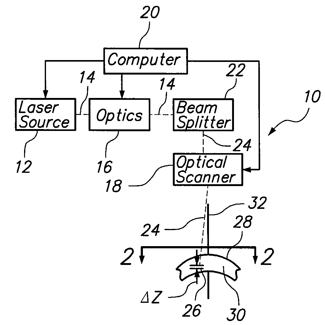
[0036]Referring initially to FIG. 1, a system for dispersing focal spots on a spiral path through a treatment area during ophthalmic laser surgery is shown and is generally designated 10. As shown, the system 10 includes a laser source 12 for generating a primary laser beam 14. For purposes of the present invention, the laser source 12 can be of any type well known in the pertinent art that is capable of performing Laser Induced Optical Breakdown (LIOB) during an ophthalmic laser surgery procedure.

[0037]FIG. 1 also shows that the system 10 includes optics 16 for focusing the primary laser beam 14, and an optical scanner 18 for moving the focal point of the primary laser beam 14. Further, system 10 includes a computer 20 that coordinates the operations of the optics 16 and optical scanner 18 with that of the laser source 12. System 10 also includes a beam splitter 22 for converting the primary laser beam 14 into a multi-beam 24. As envisioned for the system 10 the beam splitter 22 ma...


PUM


Abstract

A system and method for performing ophthalmic laser surgery requires directing a laser beam through a stationary beam splitter to create a pattern of multi-focal spots. Also, a beam scanner is used to move this pattern along a substantially spiral path in a target area of tissue. To compensate for cyclical changes in orientation of the pattern relative to its spiral path, a computer is used to phase modulate pattern movement. Specifically, this phase modulation is expressed as:
v′=v(1+F sin(nθ))
where v is a variable (e.g. angular speed, line spacing, or z-spacing), v′ is the phase modulated variable, F is a magnitude factor for phase modulation control, n is an integer, and θ is an angular position of the pattern during phase modulation.

Description

[0001]This application is a continuation-in-part of pending application Ser. No. 11 / 682,976 filed Mar. 7, 2007, which is a continuation-in-part of pending application Ser. No. 11 / 190,052 filed Jul. 26, 2005, which is a continuation-in-part of pending application Ser. No. 11 / 033,967 filed Jan. 12, 2005, which is a continuation-in-part of application Ser. No. 10 / 293,226, filed Nov. 13, 2002, which issued as U.S. Pat. No. 6,887,232 on May 3, 2005. The contents of application Ser. Nos. 11 / 682,976, 11 / 190,052 and 11 / 033,967, and issued U.S. Pat. No. 6,887,232, are incorporated herein by reference.FIELD OF THE INVENTION[0002]The present invention pertains generally to systems and methods for performing ophthalmic laser surgery. More particularly, the present invention pertains to systems and methods for performing ophthalmic laser surgery using multiple focal spots. The present invention is particularly, but not exclusively, useful as a system and method for moving a pattern of multiple f...

Claims


Application Information

Patent Timeline
IPC IPC(8): A61B18/20
CPCA61F9/008A61F9/00825A61F2009/00872A61F2009/00897
Inventor BILLE, JOSEF
Owner TECHNOLAS PERFECT VISION
Why Eureka
Try Eureka