
Peer-to-peer collaboration system with edge routing

a collaboration system and peer-to-peer technology, applied in the field of peer-to-peer collaboration system with edge routing, can solve the problems of not being able to allow peer devices, interfering with peer-to-peer communication, etc., and achieve the effects of reducing congestion, reducing the load on the relay server, and reducing the cost of a peer-to-peer collaboration system

Active Publication Date: 2008-11-20
MICROSOFT TECH LICENSING LLC
View PDF24 Cites 259 Cited by
  • Summary
  • Abstract
  • Description
  • Claims
  • Application Information

AI Technical Summary

Benefits of technology

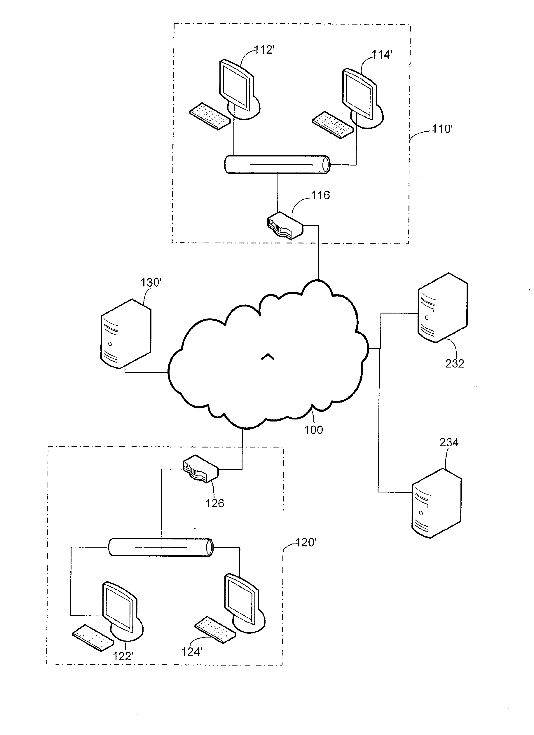
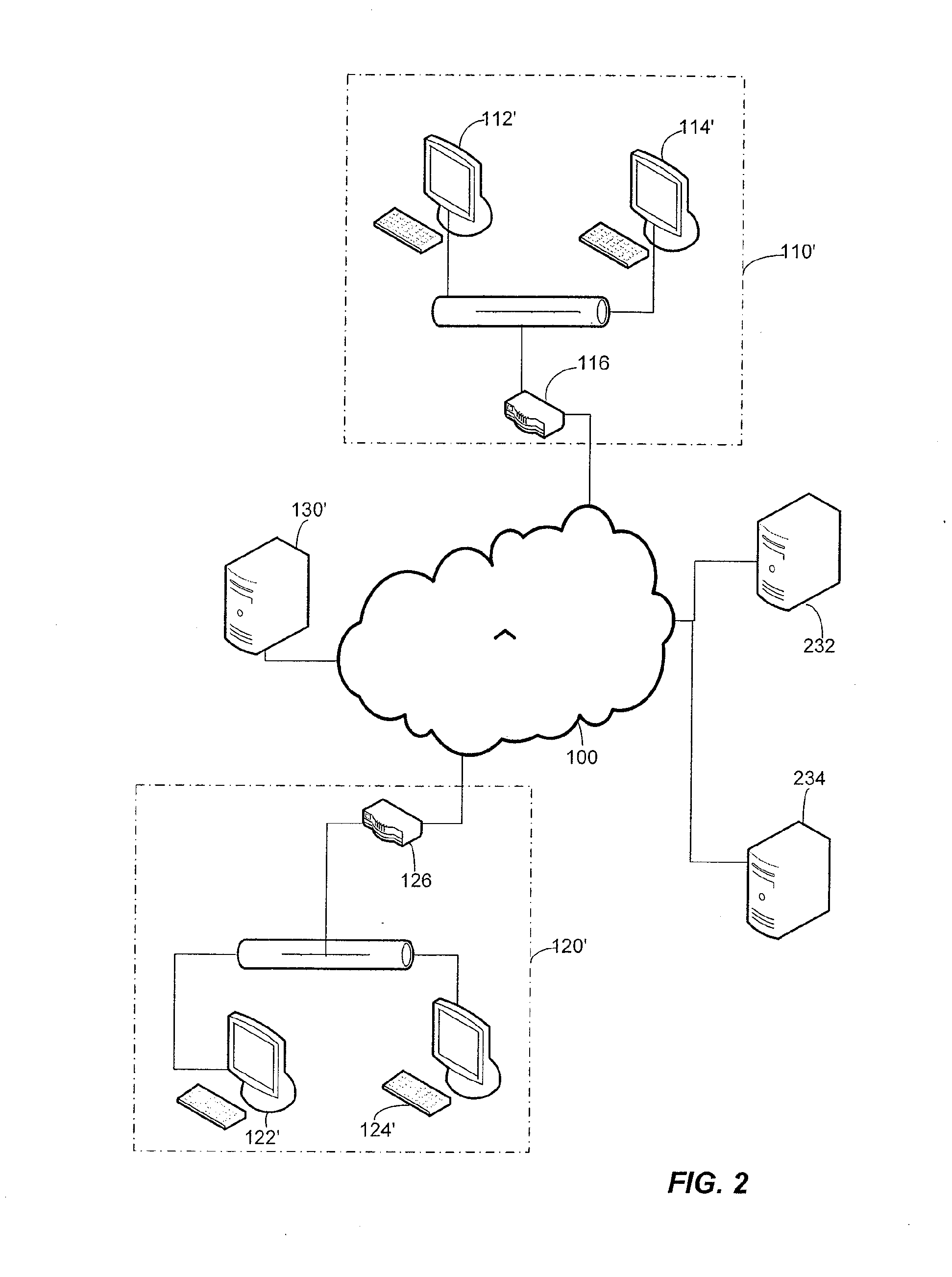
[0005]To reduce congestion caused by routing change messages through relay servers in a peer-to-peer communication session, the changes are communicated in messages that may be distributed using direct peer-to-peer messages. Though a relay server may be used for some messages, reducing the load on the relay server in handling a large number of change messages may reduce the cost of a peer-to-peer collaboration system and may increase scalability of the system.
[0007]A relay server, or other component of the collaboration system, may participate in construction of the routing table. Such a server may receive probing messages from the peers and analyze those messages to obtain information about the address at which other peers may be able to communicate with the peer. If the peer is behind a Network Address Translation (NAT) device, information obtained by the server may also be used to identify an approach to traverse the NAT device to reach the peer, potentially expanding the number of peers in a collaboration session reachable with direct peer-to-peer communication.

Problems solved by technology

However, some private networks, though coupled to the Internet, are not configured to allow peer devices coupled to the Internet through the private network to engage in peer-to-peer communications with devices outside the private network.
Address translation can disrupt messages directed to a peer behind a NAT device, thereby interfering with peer-to-peer communication.

Method used


Image

  • Peer-to-peer collaboration system with edge routing
  • Peer-to-peer collaboration system with edge routing
  • Peer-to-peer collaboration system with edge routing

Examples


Embodiment Construction

[0018]The inventors have appreciated that using a relay server to facilitate indirect communication between peers that cannot directly communicate in a collaboration session of a peer-to-peer collaboration system can create an undesirable amount of load around a relay server. As a result, effective operation of a peer-to-peer collaboration system may require an undesirable amount of resources, such as network bandwidth or memory, associated with a relay server. The inventors have also recognized that load, and performance degradation associated with server load, increases as more peer devices are unreachable by other peer devices. One reason that a peer device may be unreachable for direct communication is that the peer may be behind a NAT device. Unfortunately, the likelihood that a peer device is behind a NAT device has increased as more users work from home or are connected to the Internet through local area networks that employ NAT devices.

[0019]According to embodiments of the i...


PUM


Abstract

A peer-to-peer collaboration system in which changes to a shared space may be broadcast to all of the peers in a collaboration session using messages sent with a combination of addressing techniques. Messages may be addressed for direct peer-to-peer transmission, indirect transmission through another peer or indirect transmission through a server. The type of addressing used to communicate with each peer is determined through the use of a routing table. The routing table defines interconnected groups of peers and may be used to select one or more peers in each group as the initial recipients of the message. The initial recipients may forward the message to other peers within their groups, such that all peers receive the message. For peers behind a NAT, one or more NAT traversal techniques may be used to obtain information to construct the routing table.

Description

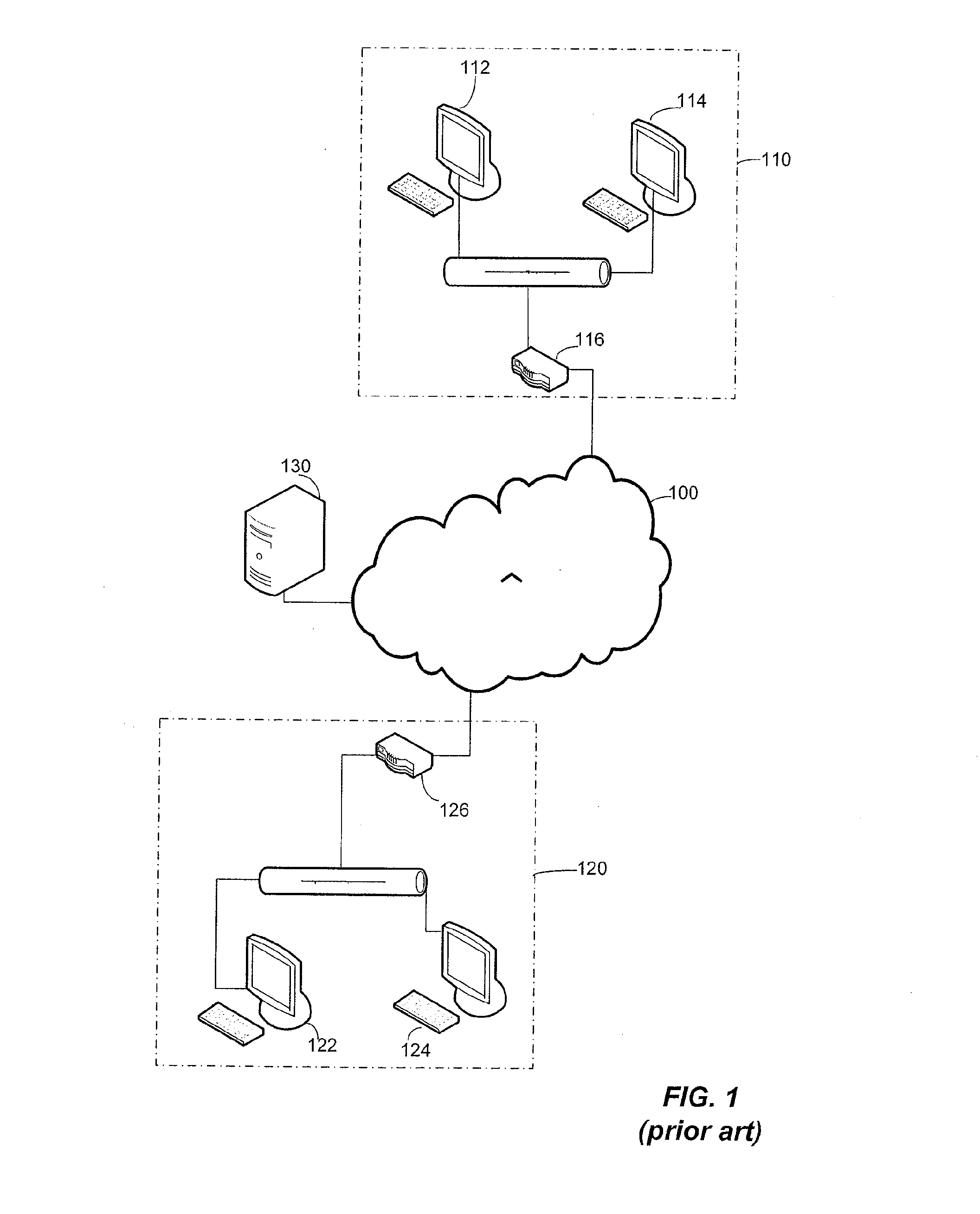
BACKGROUND[0001]Peer-to-peer collaboration systems are used, generally in business settings, to allow multiple users to work collaboratively even though the users may be in different locations. A peer-to-peer collaboration system is implemented with computing devices interconnected by a network. Each of the peer devices may maintain a copy of data or other information that is displayed to or acted on by the collaborating users. That information creates what is called a “shared space.”[0002]Client software in each of the peer devices allows the user of that device to change the copy of the shared space maintained by that device. As each change is made, the client broadcasts messages indicating the changes made to the shared space. Other peer devices in a collaboration session receive those change messages and make corresponding changes to their copies of the shared space. In this way, all of the copies of the shared space are synchronized and every user in the collaboration session c...

Claims


Application Information

Patent Timeline
IPC IPC(8): G06F15/16
CPCH04L29/12509H04L29/12528H04L29/12537H04L61/2567H04L67/1068H04L61/2578H04L63/029H04L67/104H04L67/1051H04L61/2575
Inventor WANG, JIM J.TITCHENER, THOMAS B.SANFILIPPO, THOMAS D.
Owner MICROSOFT TECH LICENSING LLC
Learn More